
Digital cam continuous zooming system

A zoom system and cam technology, applied in optical elements, optics, instruments, etc., can solve the problems of difficult machining, increased cost, poor accuracy, etc., and achieve the effects of easy assurance of assembly accuracy, convenient adjustment, and simple structure

Inactive Publication Date: 2013-10-23
XI'AN INST OF OPTICS & FINE MECHANICS - CHINESE ACAD OF SCI
View PDF5 Cites 7 Cited by
  • Summary
  • Abstract
  • Description
  • Claims
  • Application Information

AI Technical Summary

Problems solved by technology

[0004] (1) The use of cams requires high precision and difficult machining, requiring high-precision machine tools and boring machines, which increases the cost
[0005] (2) The zoom slide and compensation slide are easy to wear, and long-term use will lead to a decrease in zoom accuracy
[0006] (3) Due to the adoption of the gear transmission system and the gap between the guide pin and the cam, resulting in a large backlash, the whole mechanism has problems such as large volume, low efficiency, and poor precision.
[0007] (4) After the design and processing are completed, the curve cannot be changed or adjusted

Method used


Image

  • Digital cam continuous zooming system
  • Digital cam continuous zooming system
  • Digital cam continuous zooming system

Examples


Embodiment Construction

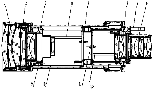
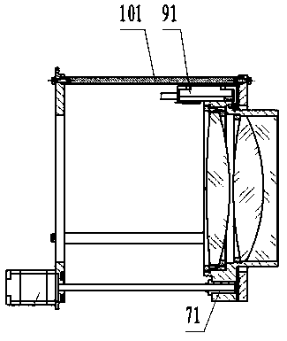
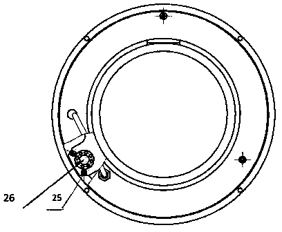
[0031] see Figure 1-8 ,

[0032] Linear drives require the following key components: linear motors, linear guides, and linear displacement sensors. Linear motors can directly convert electrical energy into linear motion mechanical energy without the need for an intermediate conversion structure transmission system, which has obvious advantages over traditional methods, such as simple structure, fast speed, and high precision.

[0033] In the scheme, the digital cam technology (motor program control) is used to replace the mechanical cam to realize the continuous zoom control method of the zoom optical lens. Use the computer to control the drive motor according to the zoom equation, so that each moving mirror group in the zoom lens can obtain the required linear or nonlinear precise displacement, ensure the stability of the image plane, obtain satisfactory imaging results, and output accurate focal length values ​​at the same time. To meet the needs of equipment for measurem...


PUM


Abstract

The invention relates to a digital cam continuous zooming system which comprises a fixing frame, a focusing assembly, a compensation assembly, a times changing assembly, a first guide rod and a second guide rod, wherein the focusing assembly and the compensation assembly are arranged at the two ends of the fixing frame respectively, the times changing assembly is arranged between the focusing assembly and the compensation assembly, the first guide rod is used for the times changing assembly to do reciprocating rectilinear motion, and the second guide rod is used for the compensation assembly to do reciprocating rectilinear motion; a front mirror assembly is arranged at one end of the focusing assembly, a dimming assembly and a rear mirror assembly are sequentially arranged at one end of the compensation assembly, and a precision screw rod output linear motor providing a power source for the first guide rod and the second guide rod is arranged between the times changing assembly and the compensation assembly. The digital cam continuous zooming system is low in cost, high in precision, small in size and adjustable.

Description

technical field [0001] The invention belongs to the field of optical mechanics and relates to a zoom system, in particular to a digital cam continuous zoom system. Background technique [0002] Mechanically compensated continuous zoom optical system, the traditional method is mainly to use a mechanical cam mechanism to realize the continuous zoom of the zoom optical lens. There are various types of mechanical cams, which are divided into three types: disc cams, moving cams, and cylindrical cams according to the cam shape. In the lens movement mechanism, a cylindrical cam is mainly used. There are two groups of curved grooves on the circumference of the cam, and the two groups of grooves are processed according to the optical performance curve, so that when the zoom group moves, the compensation group moves accordingly for compensation. [0003] In the mechanical cam mechanism, there are mainly rotating motors, cams, guide pins, moving mirror groups, and outer lens barrels ...

Claims


Application Information

Patent Timeline
Patent Type & Authority Applications(China)
IPC IPC(8): G02B15/00
Inventor 王苗郝伟姚大为曹焱
Owner XI'AN INST OF OPTICS & FINE MECHANICS - CHINESE ACAD OF SCI
Learn More