Method for detecting open-circuit fault of inverter circuit
An open-circuit fault and detection method technology, applied in the direction of measuring electricity, measuring devices, measuring electrical variables, etc., can solve problems such as increasing cost, and achieve the effect of realizing nonlinear mapping and simple and effective judgment.
- Summary
- Abstract
- Description
- Claims
- Application Information
AI Technical Summary
Problems solved by technology
Method used
Image

Examples
Embodiment Construction
[0019] Below in conjunction with accompanying drawing and specific embodiment, further illustrate the present invention, should be understood that these embodiments are only for illustrating the present invention and are not intended to limit the scope of the present invention, after having read the present invention, those skilled in the art will understand various aspects of the present invention Modifications in equivalent forms all fall within the scope defined by the appended claims of this application.
[0020] The "upper bridge arm" mentioned in the claims, specification and drawings of the specification refers to the side close to the positive pole of the input voltage.
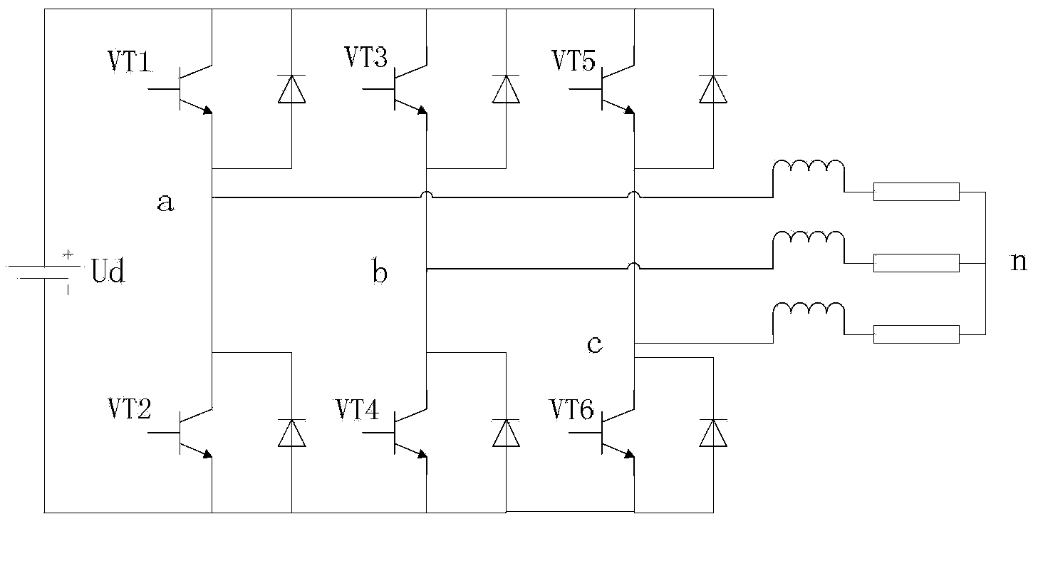
[0021] The equivalent topology of the voltage source inverter circuit is as follows: figure 1 As shown, the switching device of the inverter circuit is IGBT, the overall structure is a three-phase full bridge, and the output terminal of the circuit is connected with a load. The short-circuit fault of...
PUM
 Abstract
Description
Claims
Application Information
 - R&D
- Intellectual Property
- Life Sciences
- Materials
- Tech Scout
- Unparalleled Data Quality
- Higher Quality Content
- 60% Fewer Hallucinations
Browse by: Latest US Patents, China's latest patents, Technical Efficacy Thesaurus, Application Domain, Technology Topic, Popular Technical Reports.
© 2025 PatSnap. All rights reserved.Legal|Privacy policy|Modern Slavery Act Transparency Statement|Sitemap|About US| Contact US: help@patsnap.com