Energy measuring method and device for radio frequency card reader, and energy measuring instrument

A radio frequency card reader, energy measurement technology, applied in the field of communication, can solve the problem that the radio frequency card cannot be used normally

Active Publication Date: 2013-10-23
EASTCOMPEACE TECH
View PDF4 Cites 0 Cited by
  • Summary
  • Abstract
  • Description
  • Claims
  • Application Information

AI Technical Summary

Problems solved by technology

[0005] The invention provides an energy measurement method, device and energy measuring instrument for a radio frequency card reader. The method can measure the energy emitted by different types of radio frequency card readers, thereby assisting engineers to solve the problem of the reason why the radio frequency card cannot be used normally

Method used


Image

  • Energy measuring method and device for radio frequency card reader, and energy measuring instrument
  • Energy measuring method and device for radio frequency card reader, and energy measuring instrument
  • Energy measuring method and device for radio frequency card reader, and energy measuring instrument

Examples


no. 1 example

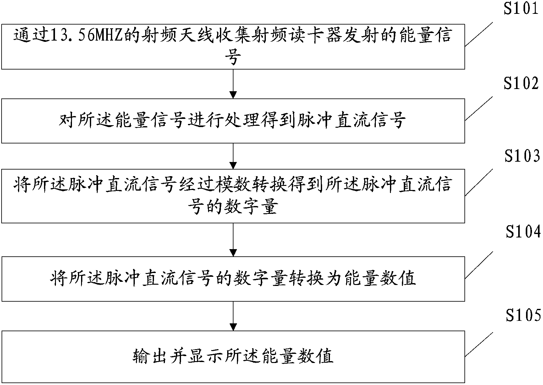
[0049] Such as figure 1 As shown, the present invention provides a first embodiment of an energy measurement method of a radio frequency card reader, comprising the following steps:

[0050] Step S101: collect the energy signal emitted by the radio frequency card reader through the radio frequency antenna of 13.56MHZ;

[0051] Before using the 13.56MHZ RF antenna to collect the energy emitted by the RF card reader, it is necessary to place the 13.56MHZ RF antenna in parallel with the RF antenna inside the RF card reader, because when the two RF antennas are placed in parallel, the 13.56MHZ RF antenna In order to accurately receive the energy emitted by the RF card reader, if there is an angle between the 13.56MHZ RF antenna and the RF antenna of the RF card reader, as the angle increases, the energy received by the 13.56MHZ RF antenna will decrease. Gradually weaken, when the angle between the RF antenna of 13.56MHZ and the RF antenna of the RF card reader reaches 90°, the RF...

no. 2 example

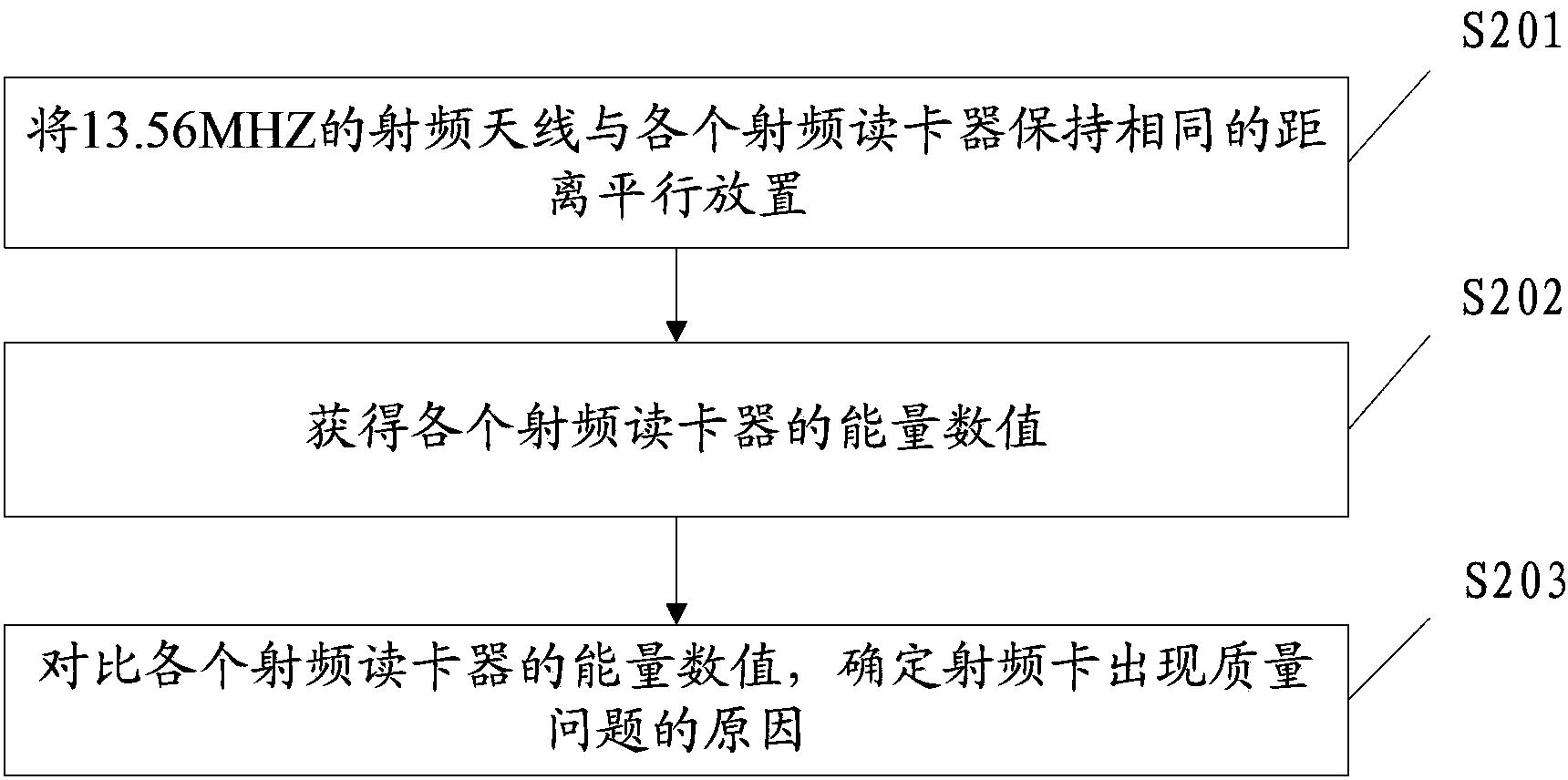
[0064] Such as figure 2 As shown, the present invention also provides the second embodiment of the energy measurement method of the radio frequency card reader, including:

[0065] Step S201: place the 13.56MHZ radio frequency antenna in parallel with each radio frequency card reader at the same distance;

[0066] Because the same RF card will be used normally on one RF card reader, but not on another RF card reader, it is necessary to measure the energy of different RF card readers on the same RF card reader. Whether the intensity of the energy varies greatly over the distance.

[0067] Because the energy emitted by the radio frequency card reader will gradually weaken with the increase of the distance, so in order to make the energy values ​​obtained by each radio frequency card reader comparable, the 13.56MHZ radio frequency antenna and different radio frequency card readers Keep the same distance so that the data obtained in the subsequent process are comparable.

[00...


PUM


Abstract

The invention provides an energy measuring method and an energy measuring device for a radio frequency card reader, and an energy measuring instrument. According to the energy measuring method provided by the invention, energy signals emitted by the radio frequency card reader are collected through a 13.56 MHZ radio frequency antenna, the energy signals are processed to obtain pulse direct current signals, the pulse direct current signals are subjected to analog-to-digital conversion, the digital quantity of the pulse direct current signals is obtained and is converted into the energy value, and the energy value is output and displayed. Engineers can obtain the emitted energy intensity of the radio frequency card reader by the method, further, whether the energy emitted by the radio frequency card reader is high enough or not is judged, so the engineers can be assisted to solve the problem that a radio frequency card cannot be normally used.

Description

technical field [0001] The invention belongs to the field of communication, and in particular relates to an energy measuring method and device of a radio frequency card reader and an energy measuring instrument. Background technique [0002] With the continuous advancement of existing technology and human life, radio frequency cards in the 13.56MHz frequency band are widely used, such as: meal cards in school cafeterias, bath cards in baths, time cards for company employees, parking cards in parking lots, and card cards for highways. Toll cards, etc., because the radio frequency cards in the 13.56MHz frequency band (hereinafter referred to as radio frequency cards) can be used in all walks of life in society, with the application of radio frequency cards, the quality of life and living standards of human beings are gradually improving, so the use of radio frequency cards is increasing. At the same time, the number of radio frequency card readers used in conjunction with radi...

Claims


Application Information

Patent Timeline
Patent Type & Authority Applications(China)
IPC IPC(8): G01R29/08
Inventor 党飞施伟周
Owner EASTCOMPEACE TECH
Why Eureka
Try Eureka