
Novel micro-accelerometer based on mesoscopic piezoresistive effect

A micro-accelerometer and acceleration technology, which is applied in the direction of acceleration measurement using inertial force, can solve the problems of unsuitable continuous testing, reduction of indicators such as sensitivity and resolution, slow return to zero, etc., to promote the improvement of detection accuracy and detection sensitivity. Improve and reduce the effect of lateral interference

Inactive Publication Date: 2013-10-23
ZHONGBEI UNIV
View PDF2 Cites 14 Cited by
  • Summary
  • Abstract
  • Description
  • Claims
  • Application Information

AI Technical Summary

Problems solved by technology

Among them, the common features of the first two are: the improvement of sensitivity depends on the reduction of structural stiffness, high sensitivity is accompanied by small range, low overload, and capacitive type is also prone to pull-in and breakdown in miniaturized applications. question
In addition, as the size of the sensor decreases, its effective sensitive area also decreases, and its sensitivity and resolution indicators are also significantly reduced, which has reached or approached the limit of its sensitive perception, thus limiting the further improvement of detection sensitivity.
The sensitivity of the piezoelectric effect nano sensor is easy to drift, requires frequent calibration, and is slow to return to zero, so it is not suitable for continuous testing
Tunnel effect nanosensors, the manufacturing process is complicated, the range is limited by the principle, the detection circuit is relatively difficult to implement, the yield is low, and it is not conducive to integration
Due to various deficiencies in traditional detection methods, the limited micro accelerometers are developing in the direction of miniaturization and integration, which is difficult to meet the needs of modern military and civilian equipment

Method used


Image

  • Novel micro-accelerometer based on mesoscopic piezoresistive effect
  • Novel micro-accelerometer based on mesoscopic piezoresistive effect
  • Novel micro-accelerometer based on mesoscopic piezoresistive effect

Examples


Embodiment Construction

[0025] The embodiments of the present invention are described in detail below. Examples of the embodiments are shown in the accompanying drawings, in which the same or similar reference numerals indicate the same or similar elements or elements with the same or similar functions. The embodiments described below with reference to the drawings are exemplary, and are only used to explain the present invention, but should not be understood as limiting the present invention.

[0026] In the description of the present invention, it should be understood that the terms "center", "upper", "lower", "front", "rear", "left", "right", etc. indicate the orientation or positional relationship based on the attachment The orientation or positional relationship shown in the figure is only for the convenience of describing the present invention and simplifying the description, rather than indicating or implying that the device or element referred to must have a specific orientation, be constructed a...


PUM


Abstract

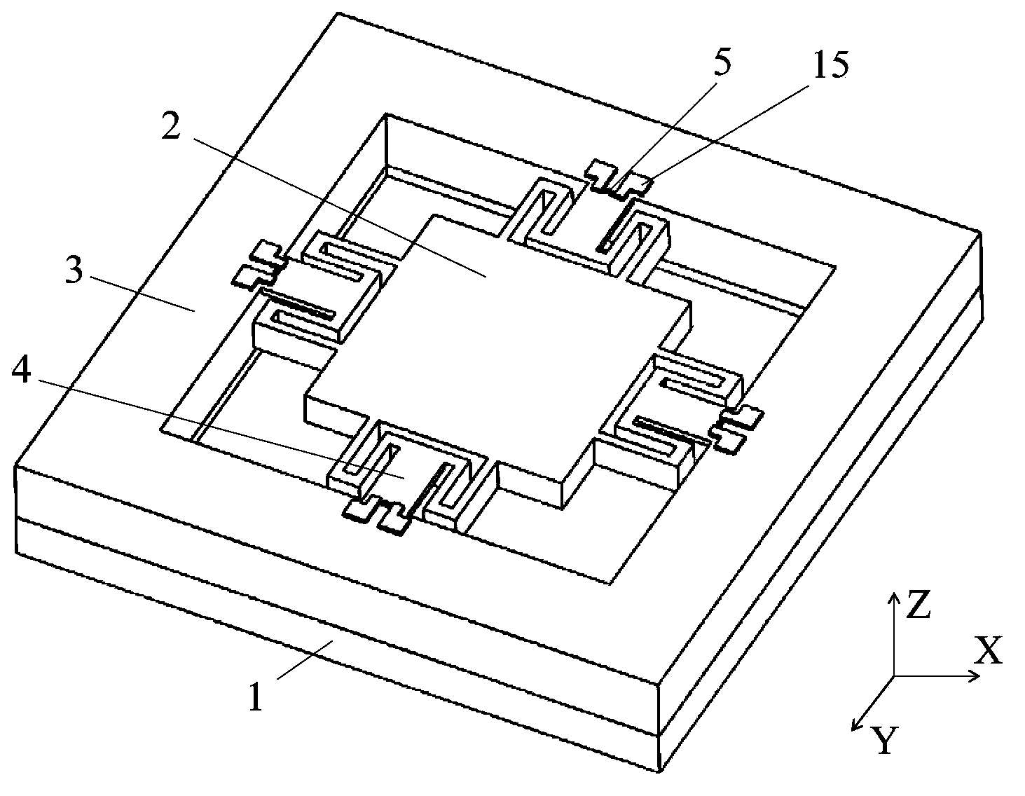
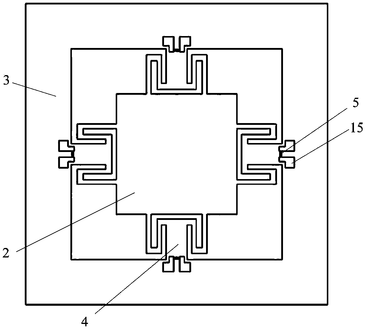
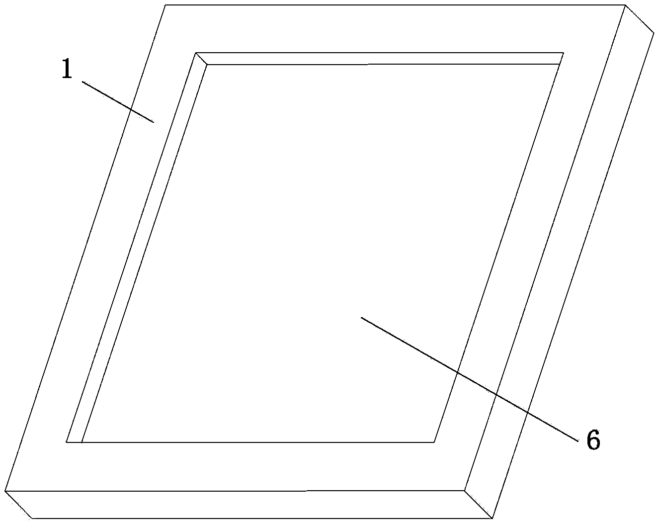
A novel micro-accelerometer based on the mesoscopic piezoresistive effect is mainly and structurally composed of a bonding substrate, a sensitive mass block, a supporting frame body, resonant tunneling devices and combined beams. Each resonant tunneling deice is composed of a resonant tunneling material thin film layer, a resonant tunneling device positive pole and a resonant tunneling device negative pole. Each combined beam is composed of a detection beam, a connection block and a transverse buffering beam. The bonding substrate serves as a carrier, the supporting frame body is bonded on the bonding substrate, the center position of each of the four edges of the supporting frame body is connected with one combined beam, one combined beam is connected to the center position of each of the four edges of the sensitive mass block, the other sides of the combined beams are connected with the supporting frame body, and each combined beam is composed of the detection beam, the connection block and the transverse buffering beam. Each resonant tunneling material thin film layer is of a multi-potential-barrier voltage-sensitive structure and can enable the sensitivity of a silicon piezoresistive device to be improved by 1-2 orders of magnitude. The novel micro-accelerometer based on the mesoscopic piezoresistive effect is reasonable and compact in structure, convenient to detect, high in precision, good in reliability and suitable for miniaturization, and has strong lateral resistance.

Description

technical field [0001] The invention relates to the research field of key components of micro-inertial navigation, in particular to a micro-accelerometer with anti-lateral interference based on resonance tunneling effect. Background technique [0002] The micromechanical accelerometer is a kind of accelerometer with small size, low power consumption and mass production. It is widely used in the military and civil fields to test acceleration, vibration and overload signals. In addition, it is also used to measure the attitude of space moving objects. One of the key components of control and control, has been highly valued by the aerospace field. [0003] Traditional micro accelerometers can be divided into: capacitive, piezoresistive, tunnel effect, piezoelectric, etc. according to the sensitive principle. Among them, the common features of the first two are: the improvement of sensitivity depends on the reduction of structural stiffness, high sensitivity is accompanied by s...

Claims


Application Information

Patent Timeline
Patent Type & Authority Applications(China)
IPC IPC(8): G01P15/12
Inventor 李孟委王莉李锡广白晓晓王琪杜康刘俊郑伦贵
Owner ZHONGBEI UNIV
Learn More