
An Optical System for Detecting the Size and Shape of Particles Using a Rotationally Symmetric Elliptical Cavity Mirror

A rotationally symmetric, optical system technology, applied in the field of optical sensors, can solve the problems affecting the shape detection accuracy, the limited acceptance angle range, and the poor light uniformity of the photosensitive area, so as to improve the detection accuracy, increase the acceptance angle range, and improve the beam uniformity. sexual effect

Inactive Publication Date: 2015-09-23
NANTONG UNIVERSITY
View PDF4 Cites 0 Cited by
  • Summary
  • Abstract
  • Description
  • Claims
  • Application Information

AI Technical Summary

Problems solved by technology

However, these instruments can only be used to measure the size of particles, and the detection of the shape is rarely involved; not only that, but these instruments also have the defects of limited acceptance angle range and poor light uniformity in the photosensitive area
For this reason, in the patent [CN201110346535.0], an optical sensor with a rotationally symmetrical elliptical cavity mirror is designed to measure the size and shape of particles. The uniformity of light has also been improved to some extent, but because the large-angle scattered light receiver only uses three photocells located at the vertices of the triangle, the amount of information collected is too small, which affects the detection accuracy of the shape, and also has a certain degree of difficulty in the detection of the size of the particles. Influence; In addition, the optical path layout adopted in this design to improve the beam uniformity is complex and easily affected by transportation, etc.

Method used


Image

  • An Optical System for Detecting the Size and Shape of Particles Using a Rotationally Symmetric Elliptical Cavity Mirror
  • An Optical System for Detecting the Size and Shape of Particles Using a Rotationally Symmetric Elliptical Cavity Mirror

Examples


Embodiment Construction

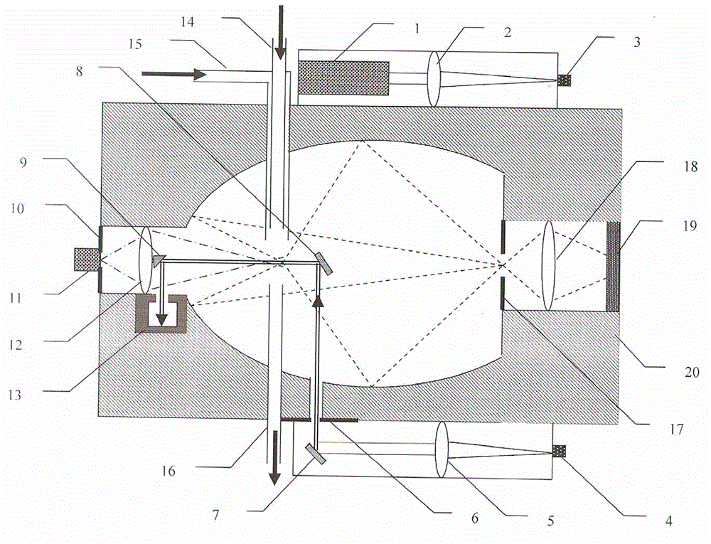
[0015] An optical system for detecting particle size and shape with a rotationally symmetrical elliptical cavity mirror, comprising a rotationally symmetrical elliptical cavity mirror 20, the elliptical cavity mirror is made of metal, and its inner surface is polished and coated with a reflective film. The laser is fixed on the outer frame, and after a certain optical path layout, it is collimated by the uniformity of the optical fiber to form a parallel beam with good uniformity, which is incident on the photosensitive area along the long axis of the rotationally symmetrical elliptical cavity mirror. The sample gas flow converges in the photosensitive area, that is, at a focal point of the rotationally symmetrical elliptical cavity mirror. The forward scattered light passes through the lens 12 and then passes through the first aperture 10 before being received by the photomultiplier tube 11. The incident beam from the original direction passes through the mirror 9 Inject into ...


PUM


Abstract

The invention discloses an optical system for detecting a microparticle size and a microparticle shape by a rotationally symmetrical ellipsoidal cavity mirror. A laser beam is homogenized through an optical fiber to form a parallel light beam having good uniformity, then the parallel light beam shoots along the main axis direction of a spherical cavity mirror system into the rotationally symmetrical ellipsoidal cavity mirror through a reasonable optical path layout, and the incident beam converges into a focus of the rotationally symmetrical ellipsoidal cavity mirror with a sample gas flow; the sample gas flow is introduced along the direction perpendicular to the main axis direction of the system, and a particle forward scattering light signal is accepted by a photomultiplier tube and is used as a main signal for particle size measurement. Scattering light except the forward scattering light shoots to another focus of the rotationally symmetrical ellipsoidal cavity mirror in a large angle scope, and a surface shaped CCD is placed on an objective lens image plane behind the focus and is mainly used for detecting particle shape information. The optical system has the advantages of clever layout, reasonable structure, and good working effect.

Description

technical field [0001] The invention relates to an optical sensor. Background technique [0002] Particle detection technology plays a vital role in scientific research, industrial sites, and atmospheric environment monitoring. Its detection technologies mainly include optical method, electrical method, and kinetic method. Among them, optical method is the most widely used for its wide measurement range, no contact with samples, fast, automatic and real-time. Typical instruments such as Coulter, Climet and ROYCO particle counter, domestic laser particle counter, etc. However, these instruments can only be used to measure the size of the particles, and the detection of the shape is rarely involved; not only that, but these instruments also have the defects of limited acceptance angle range and poor light uniformity in the photosensitive area. For this reason, in the patent [CN201110346535.0], an optical sensor with a rotationally symmetrical elliptical cavity mirror is desi...

Claims


Application Information

Patent Timeline
Patent Type & Authority Patents(China)
IPC IPC(8): G01N15/02G01B11/24
Inventor 戴兵戴未然袁银男
Owner NANTONG UNIVERSITY
Learn More