A camshaft assembly with oil and gas separation function

A technology for separating components and camshafts, applied to engine components, engine lubrication, valve devices, etc., can solve the problems of increased engine height, complex cylinder head cover structure, unfavorable engine installation and layout, etc., to achieve light weight and energy saving The effect of manufacturing costs

Active Publication Date: 2016-08-10
HANGZHOU BRANCH ZHEJIANG GEELY AUTOMOBILE RES INST +2
View PDF5 Cites 0 Cited by
  • Summary
  • Abstract
  • Description
  • Claims
  • Application Information

AI Technical Summary

Problems solved by technology

In the past, the oil-gas separation device is usually placed independently on the top of the engine cylinder head cover, which increases the height of the engine, which is not conducive to the installation and layout of the engine.
Integrating the oil-gas separation device in the cylinder head cover will make the structure of the cylinder head cover complex

Method used


Image

  • A camshaft assembly with oil and gas separation function
  • A camshaft assembly with oil and gas separation function
  • A camshaft assembly with oil and gas separation function

Examples


Embodiment Construction

[0021] In order to further explain the technical means and effects that the present invention adopts to achieve the intended purpose of the invention, the following in conjunction with the accompanying drawings and preferred embodiments, the specific implementation, structure, Features and their functions are described in detail below.

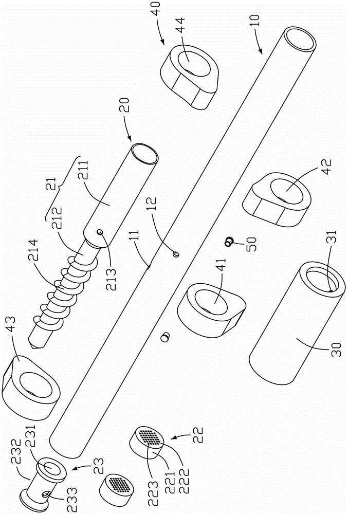
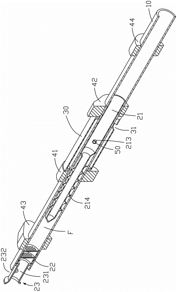
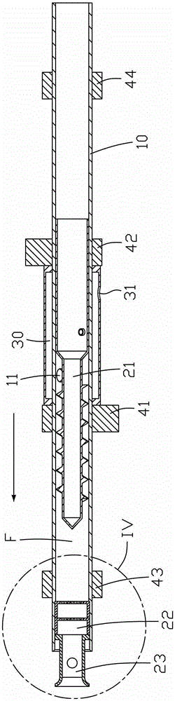
[0022] The camshaft assembly with oil-gas separation function of the present invention is fixed on the cylinder head with the camshaft bearing seat, as Figure 1 to Figure 3 As shown, the camshaft assembly includes an inner shaft 10, an oil-air separation assembly 20 disposed inside the inner shaft 10, an oil deflector sleeve 30 sleeved on the periphery of the inner shaft 10, and several cams sleeved on the inner shaft 10. 40 and the plug 50 that passes through the inner shaft 10 .

[0023] Wherein, the inner shaft 10 is a tubular structure, and the inner shaft air inlet 11 and the plugging installation hole 12 are opened on the tube wall. T...


PUM


Abstract

The invention relates to a cam shaft component with a function of oil-gas separation, which comprises an inner shaft and a plurality of cams arranged on the inner shaft, wherein the inner shaft adopts the tubular structure; the oil-gas separation component is arranged inside the inner shaft; the oil-gas separation component comprises a separation screw rod and machine oil separation cylinders all arranged inside the inner shaft. According to the cam shaft component, the oil-gas separation component is arranged inside the inner shaft, so that the oil-gas separation can be realized under the condition of not increasing the height of a motor and not increasing the complexity of an engine cylinder head; the double separation design of the separation screw rod and the machine oil separation cylinders is adopted, so as to be able to improve the oil-gas separation efficiency and lower the emission of exhaust gases of the cam shaft component.

Description

technical field [0001] The invention relates to the field of automobile engines, in particular to a camshaft assembly with oil-gas separation function. Background technique [0002] In a car's engine, the engine crankcase blow-by gas will cause the condensation of fuel vapor and water vapor, thereby deteriorating the oil and contaminating engine parts. If the blow-by gas is not exported in time, the engine will work for a long time, which will lead to excessive pressure in the crankcase, which will easily cause air leakage and oil leakage at various joints. At the same time, the engine power will increase with the increase of blow-by gas. [0003] In order to avoid the above adverse effects, the engine generally adopts an oil-gas separation device to separate the blow-by gas from oil and gas, and the separated gas is sent to the intake manifold to mix with fresh air and then enters the cylinder for combustion, and the separated oil flows back to the body , to recycle. In ...

Claims


Application Information

Patent Timeline
Patent Type & Authority Patents(China)
IPC IPC(8): F01M11/08F01L1/047
Inventor 高川刘岩沈源由毅康世邦冯擎峰
Owner HANGZHOU BRANCH ZHEJIANG GEELY AUTOMOBILE RES INST
Why Eureka
Try Eureka