Friction screw press

A screw press and friction wheel technology, applied in the field of forging, can solve problems such as instability, poor operation, and increased number of friction wheels, and achieve a compact structure

Active Publication Date: 2015-05-06
SHANGHAI YUNLIANG FORGING PRESS
View PDF6 Cites 0 Cited by
  • Summary
  • Abstract
  • Description
  • Claims
  • Application Information

AI Technical Summary

Problems solved by technology

Although this structure solves the problem of the above-mentioned lateral force, it obviously also brings new defects. First, the number of friction wheels increases, the cost increases, and it takes up space. Secondly, the lever-oil cylinder (cylinder) mechanism has both Difficult to operate and unstable

Method used


Image

  • Friction screw press
  • Friction screw press

Examples


Embodiment Construction

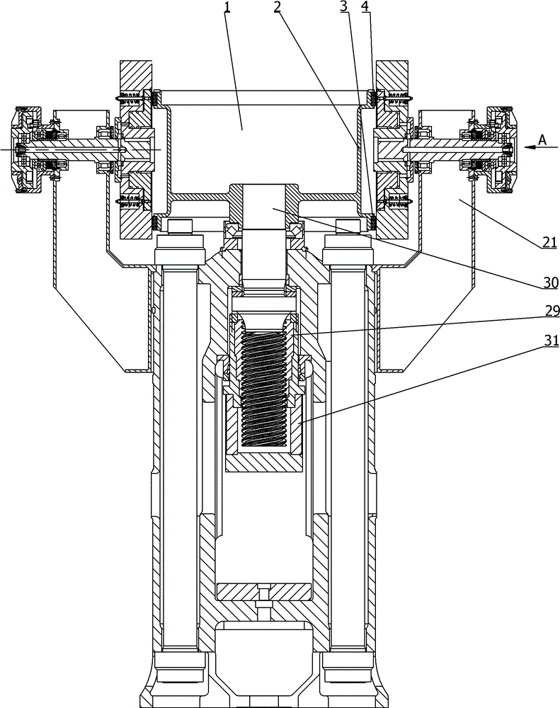
[0018] see figure 1 , is a structural schematic diagram of the screw press machine involved in the present invention. It includes a horizontally rotating flywheel 1, the flywheel 1 is connected with a screw rod 30, and the screw rod 30 and the nut 29 in the slide block 31 form a screw pair. Both sides of the flywheel 1 are symmetrically provided with friction drive devices, which are installed on the frame 21 .

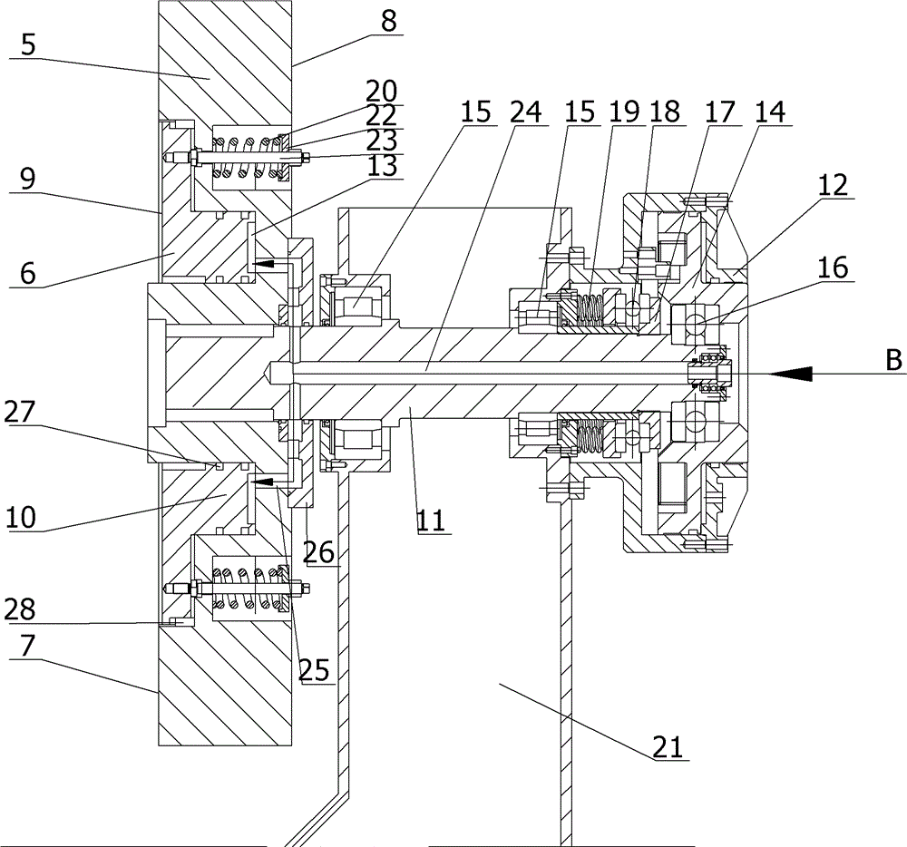
[0019] see figure 2 ,for figure 1 Enlarged view of part of . The flywheel 1 includes a flywheel body 2, and a first edge 3 and a second edge 4 are provided on the outer end surface of the body 2. Specifically, the first edge 3 and the second edge 4 are flanges protruding radially outward from the bottom and top of the flywheel body 2 . The positions of the friction wheels 5 and 6 in the flywheel 1 and the friction drive device are as follows: the first edge 3 is opposite to the first end 7 of the first friction wheel 5, and the second edge 4 is opposite to the f...


PUM


Abstract

The invention discloses a friction screw press comprising a flywheel. The flywheel is connected with a slider through a screw pair, a first edge and a second edge are arranged on the flywheel, the first edge is arranged opposite to a first end of a first friction wheel, the second edge is arranged opposite to a first end of a second friction wheel, a rotating shaft is arranged at the center of a second end of the first friction wheel, the rotating shaft is hermetically connected with a first cylinder, a first return mechanism is arranged between the rotating shaft and the first cylinder, a chamber serving as a second cylinder is further arranged at the first end of the first friction wheel, the second cylinder is hermetically connected with a second end of the second friction wheel, the second friction wheel rotates along with the first friction wheel, and a second return mechanism is further arranged between the first friction wheel and the second friction wheel. The friction screw press is compact in structure due to the design of the first and second friction wheels, the first cylinder and the second cylinder are designed skillfully, the first friction wheel and the second friction wheel can rotate simultaneously, and the first friction wheel can move axially relative to the first friction wheel.

Description

technical field [0001] The invention belongs to the field of forging, and in particular relates to a screw press. Background technique [0002] In the traditional friction screw press, one friction wheel is arranged on both sides of the flywheel, one is used to depress the slider, and the other is used to lift the slider. During the forging process, the two friction wheels act alternately. When the friction wheel is pressed down, the flywheel is pressed, and at the same time, the friction wheel is lifted to disengage from the flywheel, and the flywheel drives the slider to carry out forging downward; , the flywheel rotates in the opposite direction and drives the slider back up. The defect of this type of friction wheel is that, because the friction wheel on one side acts on the flywheel every time, there is a large lateral force, the copper nut on the screw rod is seriously damaged, and the forgeability is also low. [0003] There is a kind of improved screw press again a...

Claims


Application Information

Patent Timeline
Patent Type & Authority Patents(China)
IPC IPC(8): B21J9/18
Inventor 陆友荣龚伟兴
Owner SHANGHAI YUNLIANG FORGING PRESS
Why Eureka
Try Eureka