
High-efficiency jaw plate with rear-mounted base

A rear-mounted, high-efficiency technology, applied in the direction of grain processing, etc., can solve the problems of insufficient strength of the base, affecting the matching accuracy, unreasonable layout design of "frame" and "space", and achieve the goal of increasing rigidity and enhancing crushing function Effect

Inactive Publication Date: 2013-10-23
YIWU BLACK AND WHITE MINING MACHINERY
View PDF9 Cites 3 Cited by
  • Summary
  • Abstract
  • Description
  • Claims
  • Application Information

AI Technical Summary

Problems solved by technology

[0011] The embarrassing problem encountered in designing the base structure is: the base is too thin to worry about insufficient strength, and too thick to fear material waste (because the material in the base area does not participate in substantial breaking)
But here is a technical misunderstanding, because it ignores the fact that the jaw plate is a hard material
[0015] (2) Another technical misunderstanding is: the combination of the back of the jaw plate with a square-shaped frame structure (or groove structure) and the base can strengthen the strength of the jaw plate
[0016] As mentioned above, the frame at the back has the disadvantage of cutting and milling the plane of the frame, which affects the matching accuracy, and the "space" is wasteful and useless. The space structure should be combined with the design of the teeth, and the "space" should also be transferred to the teeth. , to deepen the tooth valley and strengthen the tooth peak to enhance the tooth shape function
[0017] To sum up, it reflects a common problem in jaw plates in the prior art, that is, the design of jaw plate structure is unreasonable, and the layout design of "frame" and "space" is unreasonable

Method used


Image

  • High-efficiency jaw plate with rear-mounted base
  • High-efficiency jaw plate with rear-mounted base
  • High-efficiency jaw plate with rear-mounted base

Examples


Embodiment 1

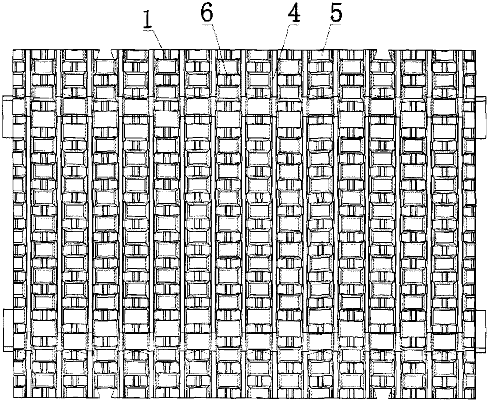
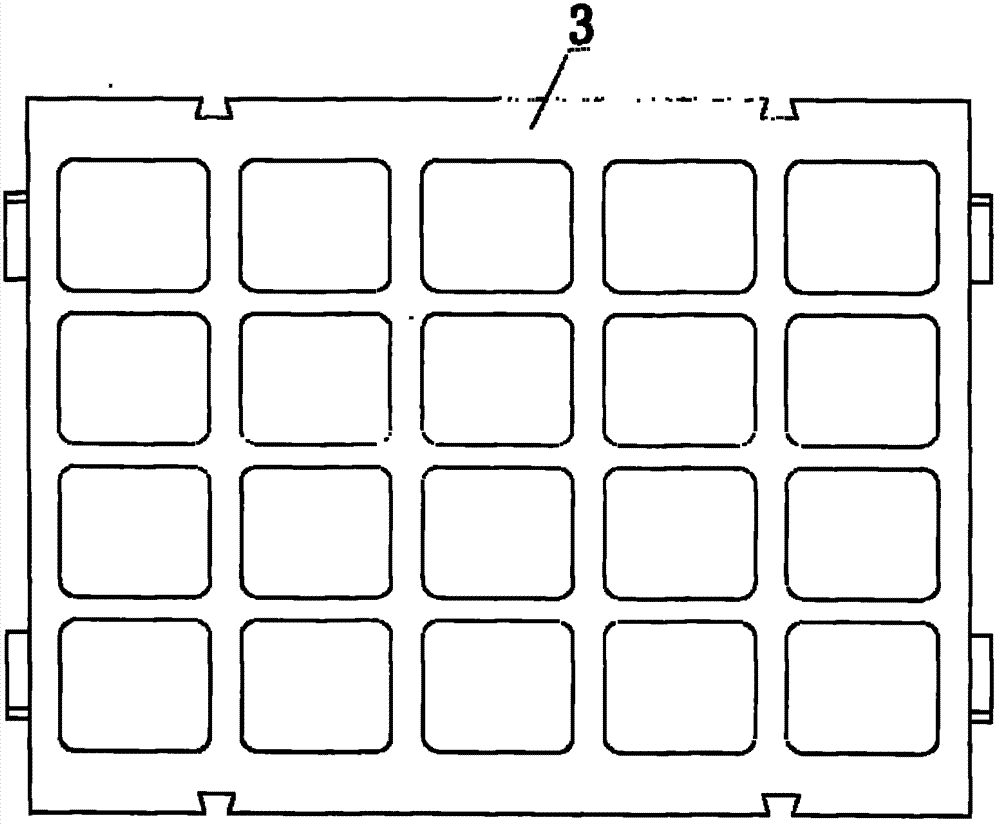
[0052] Embodiment 1: as figure 2 and image 3 As shown, a high-efficiency jaw plate with a rear base is composed of a tooth part 1, a base part 2 and a back part 3, the tooth part 1 is on the front side of the base part 2, the back part 3 is on the back side of the base part 2, and the base part 2 is set at an offset from The center line of the entire jaw is on the 3 sides of the back. There are staggered horizontal tooth peaks 6 and vertical tooth peaks 4 on the tooth portion 1, and tooth valleys 5 between the tooth peaks.

[0053] like Figure 4 As shown, the back 3 is a square frame structure with a thickness of 3 millimeters.

Embodiment 2

[0054] Embodiment 2: as Figure 4 As shown, the back 3 is a matte frame structure, and the thickness is 5 millimeters.

Embodiment 3

[0055] Embodiment 3: as Figure 5 As shown, the back 3 is a groove structure with a depth of 3 mm. All the other are with embodiment 1.


PUM


Abstract

The invention discloses a high-efficiency jaw plate with a rear-mounted base. The high-efficiency jaw plate consists of a tooth, the base and a back, wherein the tooth is arranged at the front of the base, the back is arranged at the back of the base, and the base is arranged at the side which is near the back and deviated from the center line of the whole jaw plate. The tooth peaks which are intersected with one another transversely and vertically are arranged on the tooth, and tooth dips are arranged among the tooth peaks. The 'space' in the jaw plate is taken as an element, so that the novel jaw plate structure is redistributed and redesigned in combination with the tooth-shaped design: i.e. the 'base' of the jaw plate in the prior art is arranged at the back of the jaw plate under the conditions of the same volume and weight, i.e. 'the space' in the back structure is 'moved' to the front from the back, so that the tooth dips can be deepened, and the tooth-shaped structure can be enhanced; and 'a frame material' in the back structure is converted into 'the transverse tooth peaks' of the tooth, so that the whole rigidity strength of the jaw plate can be enhanced, the crushing efficiency of the jaw plate can be improved, and the service life of the jaw plate can be prolonged.

Description

technical field [0001] The invention relates to the field of jaw crushers, more specifically to a base rear-mounted high-efficiency jaw plate Background technique [0002] Jaw crusher, also known as jaw crusher, is one of the oldest and most widely used crushing equipment. [0003] Jaw plate, also known as tooth plate. It is an important part of the jaw crusher, each jaw crusher includes two jaw plates, one fixed jaw plate and one movable jaw plate form the crushing pair. The production efficiency, crushing effect, power consumption and wear of the jaw crusher are directly related to the crushing pair composed of two tooth plates, which largely determines the performance of the entire jaw crusher. [0004] Seen from side view direction, the structure of prior art jaw plate (see figure 1 ) can be divided into three parts: teeth, base and back: [0005] 1. The tooth part is set on the front side of the jaw plate, usually in an upper and lower vertical structure. The tooth ...

Claims


Application Information

Patent Timeline
Patent Type & Authority Applications(China)
IPC IPC(8): B02C1/10
Inventor 朱兴良
Owner YIWU BLACK AND WHITE MINING MACHINERY
Learn More