Loudspeaker module group
A speaker module and speaker technology, applied in the direction of frequency/direction characteristic devices, etc., can solve the problems of reducing the low-frequency bandwidth of the speaker module, reducing the high-frequency bandwidth of the speaker module, reducing the sensitivity and output power of the speaker module, etc. Achieve the effect of improving sensitivity and output power, and improving acoustic performance
- Summary
- Abstract
- Description
- Claims
- Application Information
AI Technical Summary
Problems solved by technology
Method used
Image
Examples
Embodiment 1
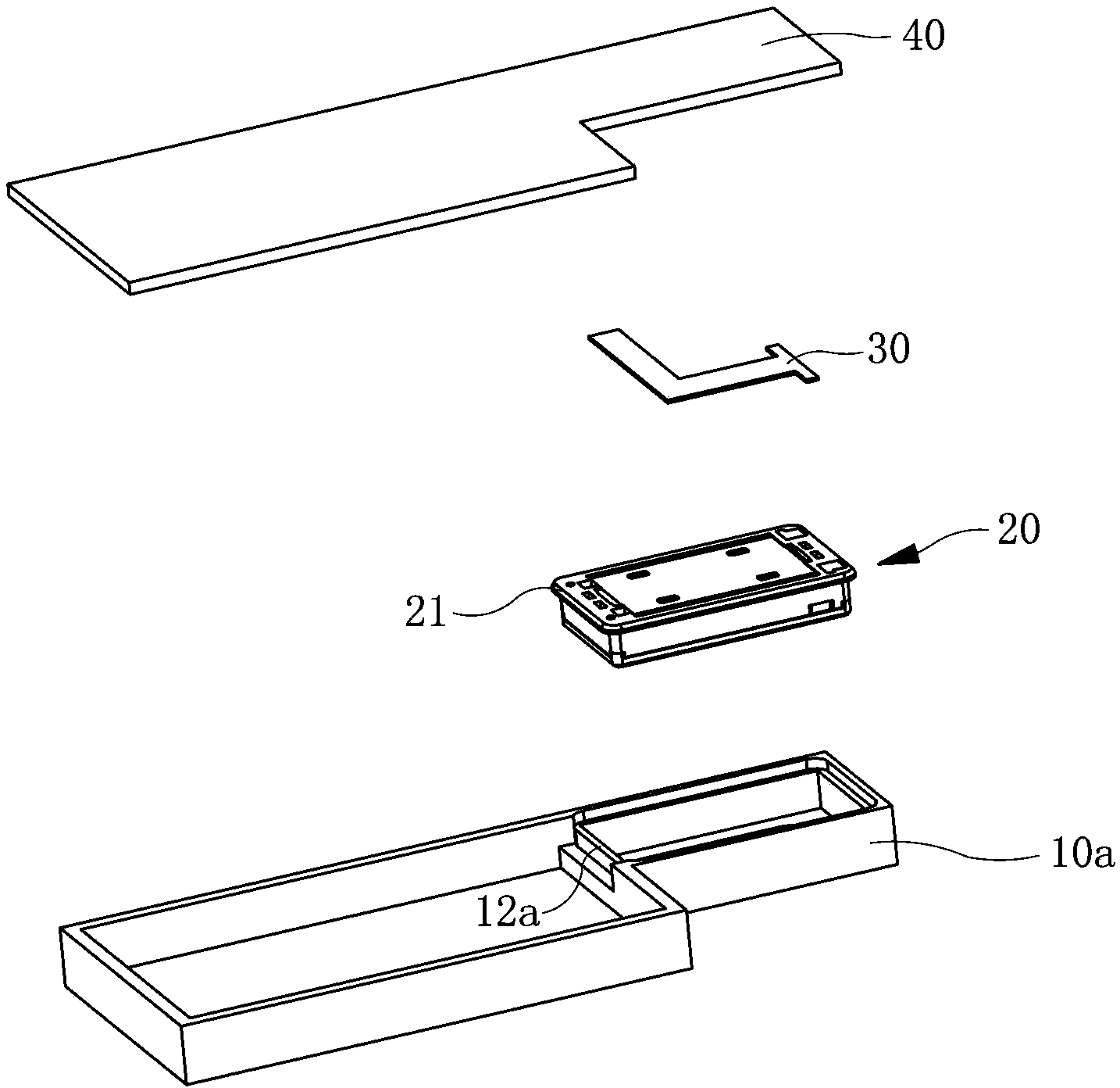
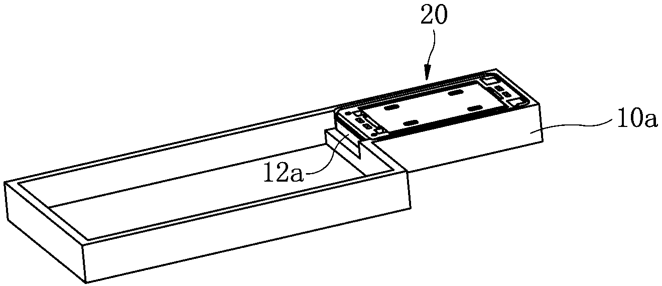
[0028] Such as figure 1 and figure 2 Commonly shown, a loudspeaker module includes a front shell 10a and a rear shell 40 combined into one, the front shell 10a and the rear shell 40 enclose a module cavity, and the module cavity is divided into two parts, one of which is smaller The loudspeaker unit 20 is accommodated in the cavity, and the larger cavity on the other side is the rear acoustic cavity, and the loudspeaker unit 20 and the rear acoustic cavity are horizontally arranged side by side. The periphery of the speaker unit 20 is provided with an annular convex edge 21 extending to the outside of the speaker unit 20, and an annular boss portion 12a is provided in the front shell 10a. The boss portion 12a is integrally structured with the front shell 10a, and the boss portion The end surface of 12a is lower than the opening end surface of front case 10a. The end surface of the convex edge 21 relative to the bottom of the front shell 10a is defined as the front end surfa...
Embodiment 2
[0040] Such as Figure 5 As shown, this embodiment is basically the same as Embodiment 1, the difference is:
[0041] The convex edge 21 is arranged on the end of the single shell 22b close to the vibration system. The front shell 10b is provided with an annular boss portion 12b. The housing 22b has an integral structure.
[0042] In this embodiment, the single shell 22b is a plastic shell; the single front cover 24a may be a plastic front cover or a metal front cover.
Embodiment 3
[0044] Such as Figure 6 As shown, this embodiment is basically the same as Embodiment 1, the difference is:
[0045] The convex edge 21 is arranged on the single front cover 24b, the front end surface of the convex edge 21 is flush with the end surface of the single front cover 24b relative to the bottom of the front shell 10c, and the front end surface of the convex edge 21 is sealed and combined with the bottom of the front shell 10c. The convex edge 21 is integrated with the single front cover 24b.
[0046] In this embodiment, the single shell 22c is a plastic shell; the single front cover 24b is a plastic front cover. In this embodiment, the structure of the front shell 10c is simpler and easier to process, and the volume of the rear acoustic cavity is larger and the acoustic performance is higher.
PUM
 Abstract
Description
Claims
Application Information
 - R&D Engineer
- R&D Manager
- IP Professional
- Industry Leading Data Capabilities
- Powerful AI technology
- Patent DNA Extraction
Browse by: Latest US Patents, China's latest patents, Technical Efficacy Thesaurus, Application Domain, Technology Topic, Popular Technical Reports.
© 2024 PatSnap. All rights reserved.Legal|Privacy policy|Modern Slavery Act Transparency Statement|Sitemap|About US| Contact US: help@patsnap.com


