
Magneto-rheological damper with asymmetrical controllable damping characteristic

A technology of magnetorheological dampers and damping characteristics, applied in shock absorbers, shock absorbers, springs/shock absorbers, etc., can solve the problems of increasing the complexity of the system and increasing the cost, so as to facilitate the popularization and use and save energy. Consumption and easy operation

Active Publication Date: 2013-10-16
CHONGQING UNIV
View PDF6 Cites 33 Cited by
  • Summary
  • Abstract
  • Description
  • Claims
  • Application Information

AI Technical Summary

Problems solved by technology

If the traditional magneto-rheological damper with symmetrical damping characteristics is used in occasions that require asymmetrical controllable damping characteristics, such as motorcycle rear suspension systems, then the controller must be used to reduce the current when the damper performs compression movement or Turn off the current, which not only requires the introduction of sensors and control circuits, but also increases the complexity of the system and increases the cost
Therefore, there is currently no corresponding magneto-rheological damper that can achieve asymmetric controllable damping characteristics for use in motorcycle rear suspensions.

Method used


Image

  • Magneto-rheological damper with asymmetrical controllable damping characteristic
  • Magneto-rheological damper with asymmetrical controllable damping characteristic
  • Magneto-rheological damper with asymmetrical controllable damping characteristic

Examples


Embodiment Construction

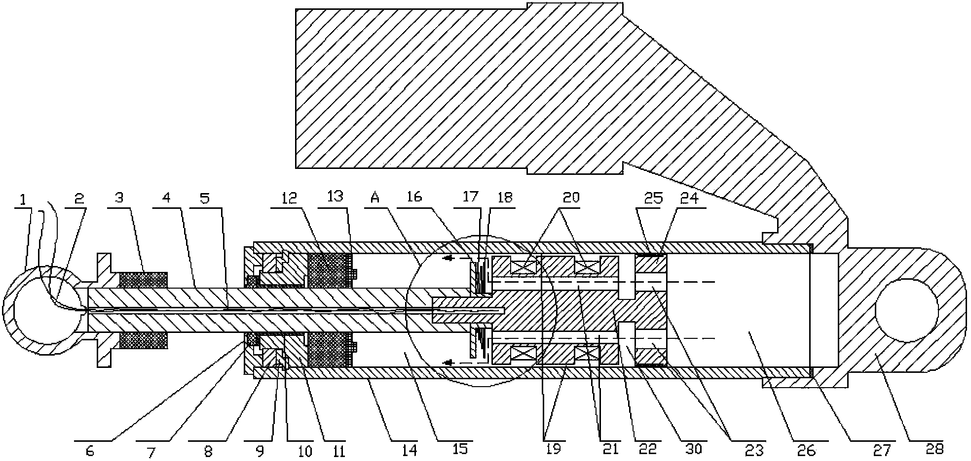
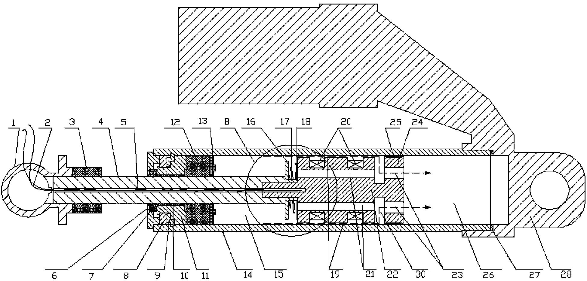
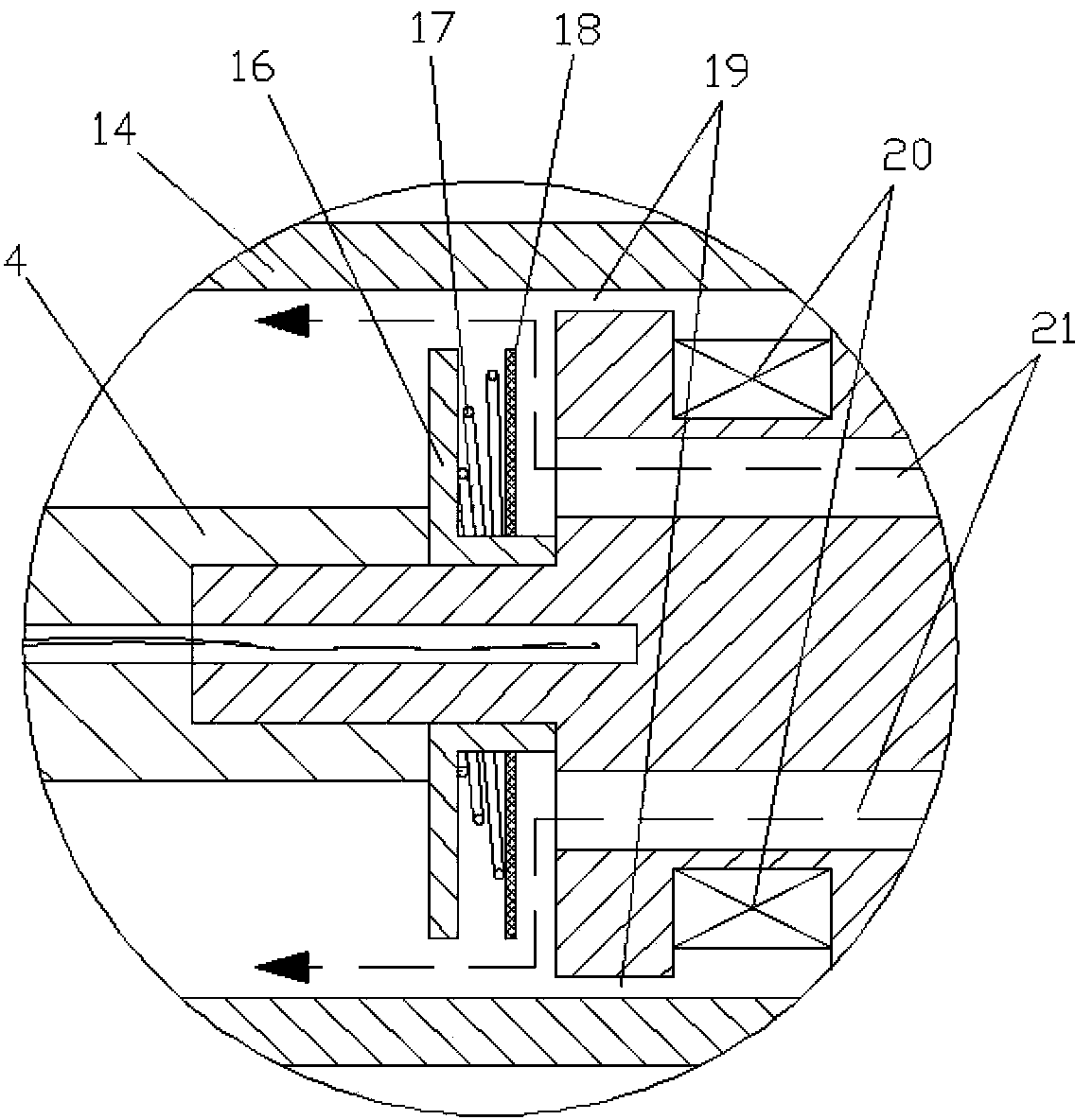
[0027] figure 1 It is a structural schematic diagram of the compression stroke of the present invention, figure 2 It is a structural schematic diagram of the recovery stroke of the present invention, image 3 for figure 1 A magnified view of A, Figure 4 for figure 2 The enlarged view of B, Figure 5 It is a schematic diagram of the monopole structure of the present invention, Image 6 It is a schematic diagram of the fixed connection structure of the piston rod extending into the piston head, Figure 7It is a schematic diagram of the fixed connection structure of the piston rod through the piston head, as shown in the figure: the magnetorheological damper with asymmetric controllable damping characteristics in this embodiment includes the magnetorheological damper body; the magnetorheological damper body includes Cylinder 14, piston rod 4, piston head 22 and magnetorheological fluid filled in the inner cavity of cylinder 14; described piston head 22 is provided with e...


PUM


Abstract

The invention discloses a magneto-rheological damper with an asymmetrical controllable damping characteristic. The magneto-rheological damper comprises a magneto-rheological damper body, wherein a piston head of the magneto-rheological damper body is provided with a magnet exciting coil and separates an inner cavity of a cylinder barrel into a first accommodating cavity close to the lower end of the cylinder barrel and a second accommodating cavity close to the upper end of the cylinder barrel; convection holes which are communicated with the first accommodating cavity and the second accommodating cavity are formed inside the piston head; and valve components which are used for performing one-way throttling on a magneto-rheological fluid from the second accommodating cavity to the first accommodating cavity are arranged in the convection holes. The magneto-rheological damper with the asymmetrical controllable damping characteristic can enable recovery and controllable damping force to be larger than compression controllable damping force, can produce larger recovery damping force under smaller current, can prolong the recovery time, and is applicable to a vibration control system such as a motorcycle rear suspension or other vehicle suspension system, which requires asymmetrical controllable damping, and semi-active vibration control is realized by changing current of the magnet exciting coil of the magneto-rheological damper; and the magneto-rheological damper is simple in structure, can realize asymmetrical controllable damping force, and is low in use cost and beneficial to popularization and utilization.

Description

technical field [0001] The invention relates to a vibration control device, in particular to a magneto-rheological damper with asymmetric controllable damping characteristics. Background technique [0002] There are three types of dampers: passive, semi-active and active. Ordinary passive dampers cannot adjust the damping force according to changes in external loads. The active control system uses sensors to obtain external load changes so that the system can output the correct damping force. The whole system is relatively complicated. Nowadays, magnetorheological technology and its semi-active control, which are more and more valued by people, combine the advantages of passive and active well, and can adjust the output damping force of the damper according to needs. [0003] The magneto-rheological damper is a shock-absorbing device used in semi-active control suspensions that has appeared in the past two decades. Magnetorheological dampers are the most widely used devic...

Claims


Application Information

Patent Timeline
Patent Type & Authority Applications(China)
IPC IPC(8): F16F9/53F16F9/34F16F9/36
Inventor 王代华刘鹏飞
Owner CHONGQING UNIV
Learn More