
Screw locking method and device

A technology of locking screws and locking screws, which is applied in metal processing, metal processing equipment, manufacturing tools, etc., can solve problems such as screw hole slippage, fast motor speed, and excessive screw torque, so as to ensure screw locking and improve The final locking torque is uncontrollable, improving the effect of the screw being broken

Active Publication Date: 2021-03-26
BEIJING A&E TECH
View PDF7 Cites 1 Cited by
  • Summary
  • Abstract
  • Description
  • Claims
  • Application Information

AI Technical Summary

Problems solved by technology

[0002] In the current automatic screw locking technology, the bit is usually directly fixed on the spindle position as the screw locking mechanism, and the servo driver is used to control the motor to drive the bit to drive the screw. However, due to the fast speed of the motor and the large inertia of the rotor, when screwing , There will be problems such as the screw being interrupted, the plum blossom groove on the nut slipping, the screw hole slipping, the screw torque being too large, etc., and the failure rate is high.

Method used


Image

  • Screw locking method and device
  • Screw locking method and device
  • Screw locking method and device

Examples


Embodiment Construction

[0017] The following will clearly and completely describe the technical solutions in the embodiments of the application with reference to the drawings in the embodiments of the application. Apparently, the described embodiments are only some of the embodiments of the application, not all of them. Based on the embodiments in this application, all other embodiments obtained by persons of ordinary skill in the art without making creative efforts belong to the scope of protection of this application.

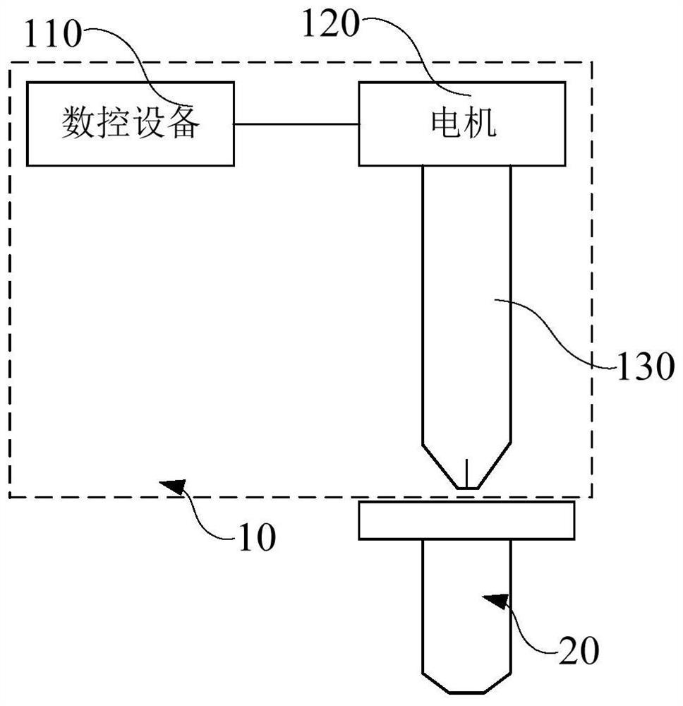
[0018] The application first proposes a locking screw device, such as figure 1 As shown, the screw locking device 10 of the present embodiment includes a numerical control device 110, a motor 120 and a bit 130, wherein the motor 120 outputs torque under the control of the numerical control device 110, and the motor 120 controls the rotation of the bit 130 with the torque to turn the bit 130 The screw 20 located at the end of the bit 130 is screwed into the screw hole.

[0019] The ...


PUM


Abstract

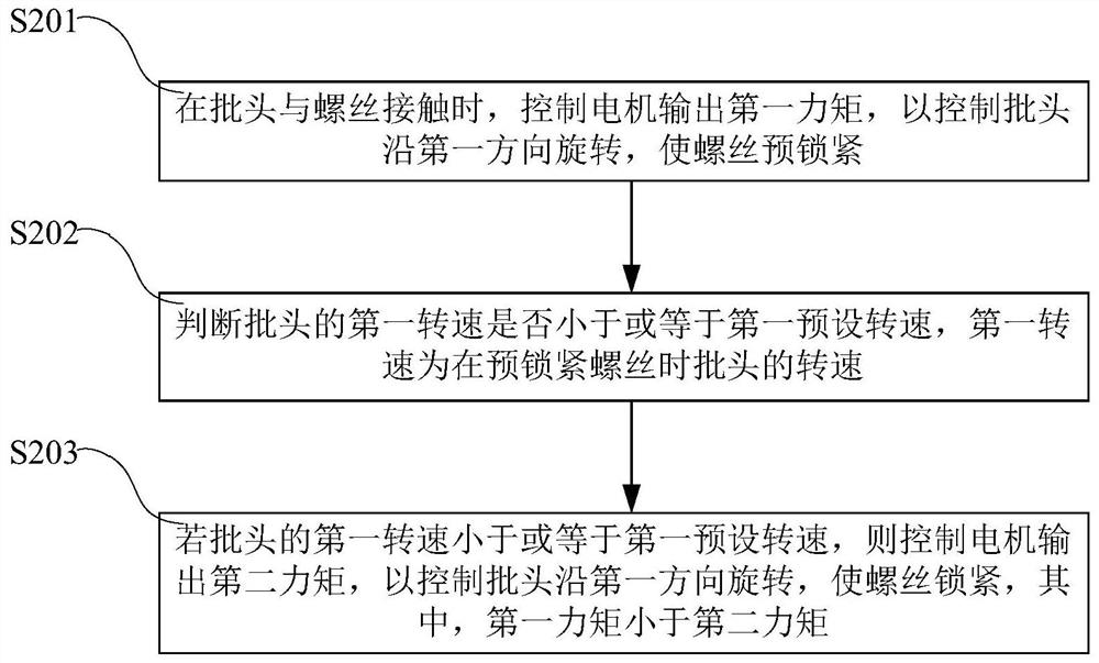
The invention discloses a screw locking method and device. The screw locking method comprises the following steps: when a screwdriver bit makes contact with a screw, controlling a motor to output first torque so as to control the screwdriver bit to rotate in the first direction, and pre-lock the screw; judging whether the first rotating speed of the screwdriver bit is smaller than or equal to a first preset rotating speed or not, wherein the first rotating speed is the rotating speed of the screwdriver bit during screw pre-locking; and if the first rotating speed of the screwdriver bit is smaller than or equal to the first preset rotating speed, controlling the motor to output second torque so as to control the screwdriver bit to rotate in the first direction to lock the screw, wherein thefirst torque is smaller than the second torque. According to the screw locking method and device, the problem that the final locking torque is uncontrollable due to the fact that inertia is too largecan be solved, so that the problems of screw breakage, stripping of a hexalobular socket in a screw cap, thread failure of a screw hole and the like can be effectively solved.

Description

technical field [0001] The present application relates to the technical field of mechanical automation, in particular to a screw locking method and a screw locking device. Background technique [0002] In the current automatic screw locking technology, the bit is usually directly fixed on the spindle position as the screw locking mechanism, and the servo driver is used to control the motor to drive the bit to drive the screw. However, due to the fast speed of the motor and the large inertia of the rotor, when screwing , There will be problems such as the screw being interrupted, the plum blossom groove on the nut slipping, the screw hole slipping, the screw torque being too large, etc., and the failure rate is high. Contents of the invention [0003] The present application proposes a screw locking method and a screw locking device to solve the above problems. [0004] In order to solve the above technical problems, a technical solution adopted by the present application ...

Claims


Application Information

Patent Timeline
Patent Type & Authority Applications(China)
IPC IPC(8): B23P19/06
CPCB23P19/06
Inventor 吴鹏
Owner BEIJING A&E TECH
Learn More