A kind of blowing roller machine

A drum machine and drum technology, applied in the direction of solid separation, separation of solids from solids by air flow, chemical instruments and methods, etc., can solve the problem of single function of the blowing machine and the inability to realize the dual functions of blowing and sediment separation, etc. problem, to achieve a reasonable effect

Active Publication Date: 2015-09-16
ZHEJIANG BORETECH
View PDF7 Cites 0 Cited by
  • Summary
  • Abstract
  • Description
  • Claims
  • Application Information

AI Technical Summary

Problems solved by technology

[0006] The present invention aims to solve the problem that the existing label blowing machine has a single function and cannot realize the dual functions of label blowing and sediment separation

Method used


Image

  • A kind of blowing roller machine
  • A kind of blowing roller machine
  • A kind of blowing roller machine

Examples


Embodiment Construction

[0025] The present invention will be further described below in conjunction with drawings and embodiments.

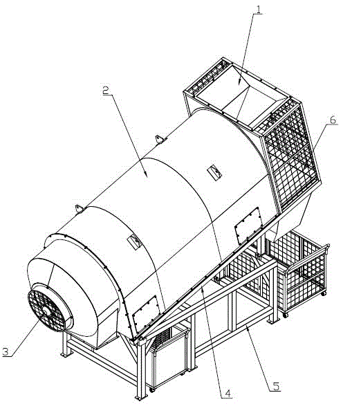
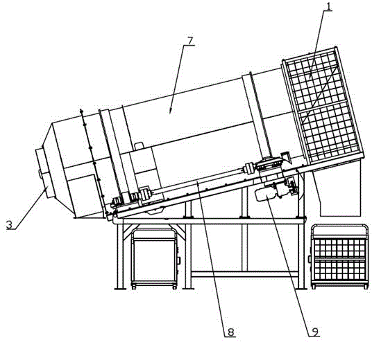
[0026] In this example, if figure 1 and figure 2 As shown, the present invention includes a reducer 9, a support, a drum 7, a machine cover 2, a hopper 1, a hopper and a fan 3; the bracket includes a lower bracket 5 and a drum bracket 4; the drum bracket 4 is provided with a main drive combination 8 It is combined with the driven transmission (not marked on the figure); the reducer 9 is connected with the main transmission combination 8; the hood 2 covers the entire drum machine device; the feeding hopper 1 is set at the entrance of the drum 7, and the fan 3 is set at the drum 7 of the exit. The roller support 4 is an inclined support, and then the cylinder 7 is placed on the roller support 4 and is also in an inclined state. The upwardly inclined end is the upper end of the cylinder, and the downwardly inclined end is the lower end of the cylinder.

[0027] Such as...


PUM


Abstract

The invention discloses a label blowing drum machine which comprises a speed reducer, a support, a drum, a machine cover, a feeding hopper, a discharging hopper and a fan. The support comprises a lower support and a drum support. A main transmission assembly and a secondary transmission assembly are arranged on the drum support. The speed reducer is connected with the main transmission assembly, the machine cover covers a whole drum machine device, the feeding hopper is arranged at an inlet of the drum, and the fan is arranged at the outlet end of the drum. The drum comprises a drum body, a drum screen and blades, wherein the outer diameter of the drum screen is smaller than the inner diameter of the drum body, the drum screen is arranged in the middle section of the drum body, and a screened object outlet is formed in the circumferential surface of the drum body. The label blowing drum machine has the function of separating labels and the function of separating sand.

Description

technical field [0001] The invention relates to a label blowing device, in particular to a label blowing drum machine capable of blowing labels and separating sediment. Background technique [0002] The working principle of the label blowing machine currently on the market is to install a fan at one end of the drum to blow the label on the plastic bottle away from the plastic bottle through a large air volume, then the label is collected, and the plastic bottle is blown from the plastic bottle under the action of the drum. The discharge port falls. The function of this blowing machine is too single to meet the needs of the market. [0003] In the Chinese patent application publication specification CN201454847U, a label blowing machine is disclosed. This label blowing machine includes a frame, a roller placed on the frame, and a motor arranged on the frame. There are blades, the front end of the drum is equipped with a fan, the rear end of the drum is equipped with a label...

Claims


Application Information

Patent Timeline
Patent Type & Authority Patents(China)
IPC IPC(8): B07B9/00
Inventor 欧哲文
Owner ZHEJIANG BORETECH
Why Eureka
Try Eureka