System for promoting ozone gas to dissolve into liquid
An ozone and gas technology, applied in the directions of dissolving, dissolving, mixers with rotary stirring devices, etc., can solve the problems of long preparation time, cumbersome operation, complicated process, etc., and achieve short preparation time, simple preparation process, and convenient preparation. Effect
- Summary
- Abstract
- Description
- Claims
- Application Information
AI Technical Summary
Problems solved by technology
Method used
Image
Examples
Embodiment 1
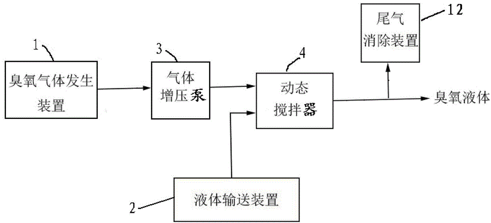
[0038] figure 1 It is a structural schematic diagram of Embodiment 1. like figure 1 As shown, the present embodiment proposes a system for promoting the dissolution of ozone gas into a liquid, including an ozone gas generator 1 for providing ozone gas, a liquid delivery device 2 for providing liquid, and a pressurization device for ozone gas A gas booster pump 3, and a dynamic agitator 4 for dynamically mixing and stirring the ozone gas and the liquid.
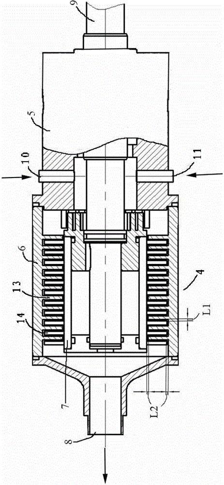
[0039] figure 2 It is the schematic diagram of the dynamic stirrer of embodiment 1. like figure 2 As shown, the dynamic mixer 4 includes: a housing 5 , a stator 6 and a rotor 7 .
[0040] One end of the casing 5 is provided with an input port for introducing the ozone gas and the liquid, and the other end of the casing 5 is provided with an output port 8 for outputting the ozone liquid.
[0041] The stator 6 is arranged in the housing 5, and the stator 6 forms a plurality of rows of stator teeth 13 in the axial direction...
Embodiment 2
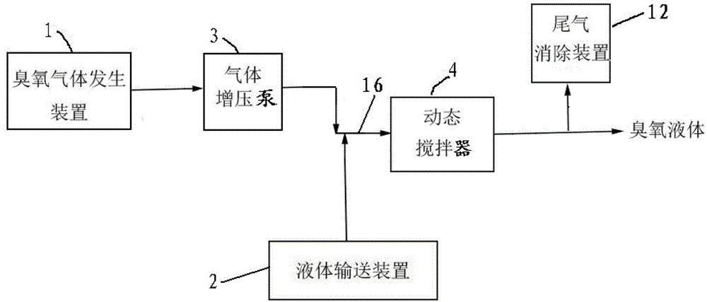
[0058] image 3 It is a structural schematic diagram of embodiment two, Figure 4 It is the schematic diagram of the dynamic mixer of embodiment two. like image 3 and Figure 4 As shown, the difference between the present embodiment and the first embodiment is that the input end of the dynamic agitator 4 of the present embodiment is a total input end 15 that simultaneously introduces the ozone gas and the liquid, and at the total input A mixing pipeline 16 is also provided at the port of the end 15. After the ozone gas generator 1 is pressurized by the gas booster pump 3, it is connected to the hydraulic delivery device 2 and connected to the mixing pipeline 16. On the mixing pipeline 16, the After preliminary mixing, it is introduced into the dynamic mixer 4 through the main input port 15 .
Embodiment 3
[0060] Figure 5 It is the schematic diagram of the dynamic mixer of embodiment three. like Figure 5 As shown, the difference between the present embodiment and the first embodiment lies in that the structure of the dynamic agitator of the present embodiment is different from that of the dynamic agitator in the first embodiment. The stator 6 in the housing 5 of the dynamic mixer 4 of this embodiment forms multiple rows of stator teeth 13 along the direction perpendicular to the axial direction, and the rotor 7 arranged in the housing 5 forms multiple rows along the direction perpendicular to the axial direction. Rotor teeth 14, combined Figure 5 It can be seen that each of the stator teeth 13 and the rotor teeth 14 extends along the axial direction, and the stator teeth 13 and the rotor teeth 14 are inserted alternately along the direction perpendicular to the axial direction. The axial distance L3 between the dedendum of each row of stator teeth 13 and the dedendum of th...
PUM
 Abstract
Description
Claims
Application Information
 - R&D
- Intellectual Property
- Life Sciences
- Materials
- Tech Scout
- Unparalleled Data Quality
- Higher Quality Content
- 60% Fewer Hallucinations
Browse by: Latest US Patents, China's latest patents, Technical Efficacy Thesaurus, Application Domain, Technology Topic, Popular Technical Reports.
© 2025 PatSnap. All rights reserved.Legal|Privacy policy|Modern Slavery Act Transparency Statement|Sitemap|About US| Contact US: help@patsnap.com


