Optical information recording medium and production method therefor
A technology for recording media and optical information, used in optical recording/reproducing, optics, data recording, etc., can solve the problems of low signal light quantity, high power loss, weakening of electronic noise, etc., and achieve excellent anti-reflection function. Effect
- Summary
- Abstract
- Description
- Claims
- Application Information
AI Technical Summary
Problems solved by technology
Method used
Image
Examples
no. 3 approach
[0098] 3. Third Embodiment (Example of Press-bonded Optical Information Recording Medium)
[0099] 4. Fourth Embodiment (First Example of Optical Information Recording Medium Having Two Information Signal Layers)
[0100] 5. Fifth Embodiment (Second Example of Optical Information Recording Medium Having Two Information Signal Layers)
[0101] 6. Sixth Embodiment (First Example in which Structures are Formed in Reading Surface of Optical Information Recording Medium)
[0102]7. Seventh Embodiment (Second Example in which Structures are Formed in Reading Surface of Optical Information Recording Medium)
[0103] 8. Eighth embodiment (first example of optical information recording medium in which the protective layer side is the reading surface)
[0104] 9. Ninth Embodiment (Second Example of Optical Information Recording Medium Where the Protective Layer Side Is the Reading Surface)
[0105] 10. Tenth embodiment (example in which structures are aligned in a square grid pattern...
no. 1 approach
[0110] [Structure of Optical Information Recording Medium]
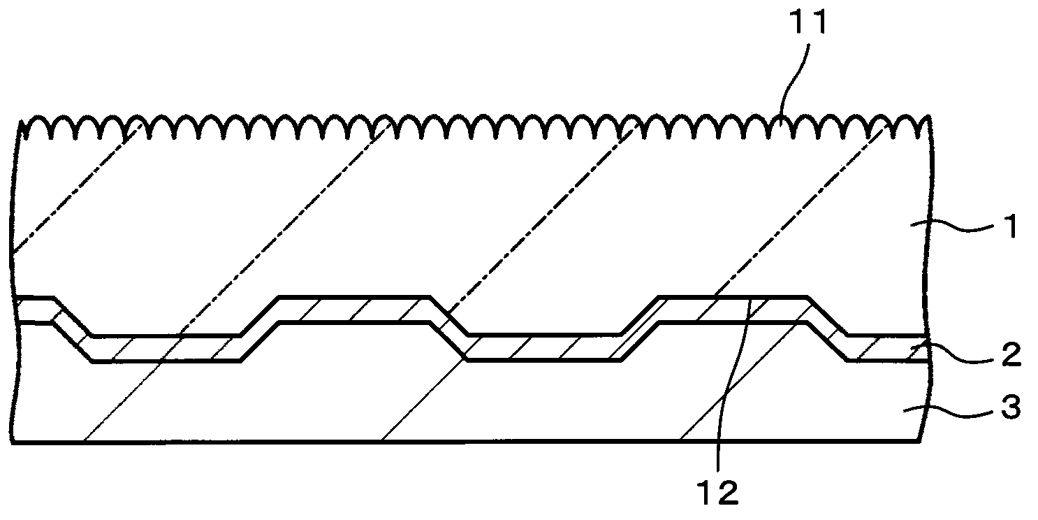
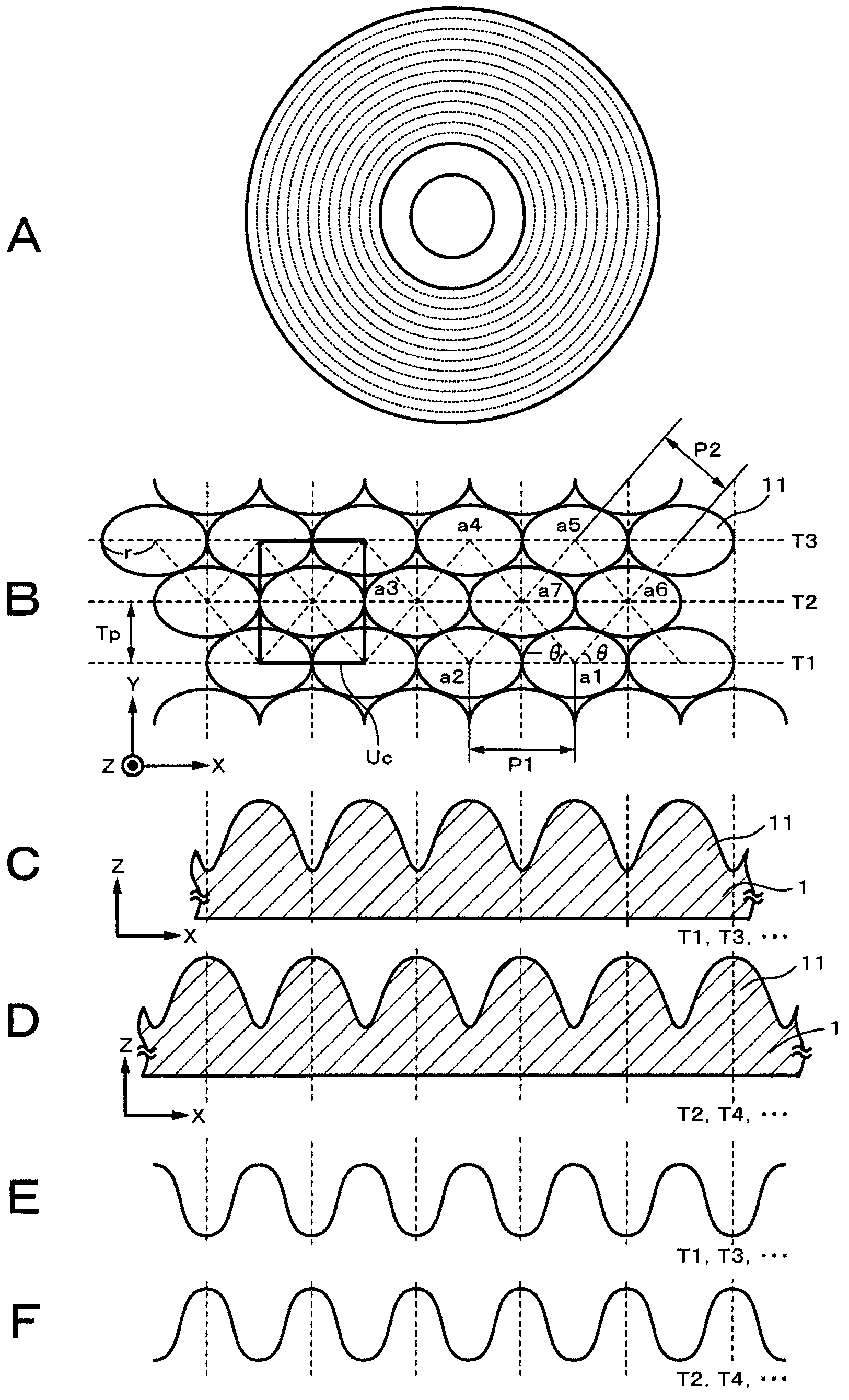
[0111] figure 1 is a sectional view showing an example of the configuration of the optical information recording medium according to the first embodiment of the present invention. This optical information recording medium has a substrate 1 , an information signal layer 2 formed on the substrate 1 , and a protective layer 3 formed on the information signal layer 2 . In the reading surface of the optical information recording medium on which laser light is irradiated, a plurality of sub-wavelength structures (hereinafter also simply referred to as “structures”) having a convex shape are formed. Meanwhile, the read surface refers to a surface on which an information signal is recorded and / or reproduced by being irradiated with laser light.
[0112] In the optical information recording medium according to the first embodiment, an information signal is recorded or reproduced by irradiating laser light to the information...
no. 2 approach
[0202] Figure 11 is a process diagram for explaining an example of the manufacturing method of the optical information recording medium according to the second embodiment of the present invention. The second embodiment of the present invention differs from the first embodiment in that the substrate 1 is formed by laminating the first molded body 1a and the second molded body 1b. In addition, parts of the second embodiment corresponding to those of the first embodiment will be assigned the same reference numerals.
[0203] (transfer process)
[0204] First, if Figure 11 As shown in A, a read surface forming master 201 is prepared. Then, if Figure 11 As shown in B, the shape of the reading surface forming master 201 is transferred to the resin material 13 according to, for example, an injection molding method. In this way, as Figure 11 As shown in C, a first formed body 1a having a plurality of structures 11 formed in one main face thereof and a flat surface formed in ...
PUM
| Property | Measurement | Unit |
|---|---|---|
| height | aaaaa | aaaaa |
| height | aaaaa | aaaaa |
| height | aaaaa | aaaaa |
Abstract
Description
Claims
Application Information
 - R&D
- Intellectual Property
- Life Sciences
- Materials
- Tech Scout
- Unparalleled Data Quality
- Higher Quality Content
- 60% Fewer Hallucinations
Browse by: Latest US Patents, China's latest patents, Technical Efficacy Thesaurus, Application Domain, Technology Topic, Popular Technical Reports.
© 2025 PatSnap. All rights reserved.Legal|Privacy policy|Modern Slavery Act Transparency Statement|Sitemap|About US| Contact US: help@patsnap.com


