
Slope compensation and loop bandwidth self-adaptation control circuit and switching power supply using same

A technology of adaptive control and slope compensation, applied in the control/regulation system, regulating electrical variables, instruments, etc., can solve the problems of poor dynamic characteristics of the control circuit, and achieve the requirements of dynamic characteristics, optimal performance, stability and stability. Effects of Dynamic Characteristics Requirements

Active Publication Date: 2013-10-09
SILERGY SEMICON TECH (HANGZHOU) CO LTD
View PDF6 Cites 13 Cited by
  • Summary
  • Abstract
  • Description
  • Claims
  • Application Information

AI Technical Summary

Problems solved by technology

[0004] In view of this, the purpose of this application is to provide a slope compensation and loop bandwidth adaptive control circuit and a switching power supply using it, so as to meet the requirements of the control circuit for stability and dynamic characteristics at the same time, and solve the problem of existing current mode control applications. The problem of poor dynamic characteristics of the control circuit of the power stage circuit

Method used


Image

  • Slope compensation and loop bandwidth self-adaptation control circuit and switching power supply using same
  • Slope compensation and loop bandwidth self-adaptation control circuit and switching power supply using same
  • Slope compensation and loop bandwidth self-adaptation control circuit and switching power supply using same

Examples


Embodiment Construction

[0045] The following will clearly and completely describe the technical solutions in the embodiments of the application with reference to the drawings in the embodiments of the application. Apparently, the described embodiments are only some of the embodiments of the application, not all of them. Based on the embodiments in this application, all other embodiments obtained by persons of ordinary skill in the art without creative efforts fall within the protection scope of this application.

[0046] The embodiment of the present application discloses a slope compensation and loop bandwidth adaptive control circuit and a switching power supply using it, so as to meet the requirements of the control circuit for stability and dynamic characteristics at the same time, and solve the problem of the existing power stage used in current mode control. The problem of poor dynamic characteristics of the control circuit of the circuit.

[0047] Embodiment 1 of the present application provid...


PUM


Abstract

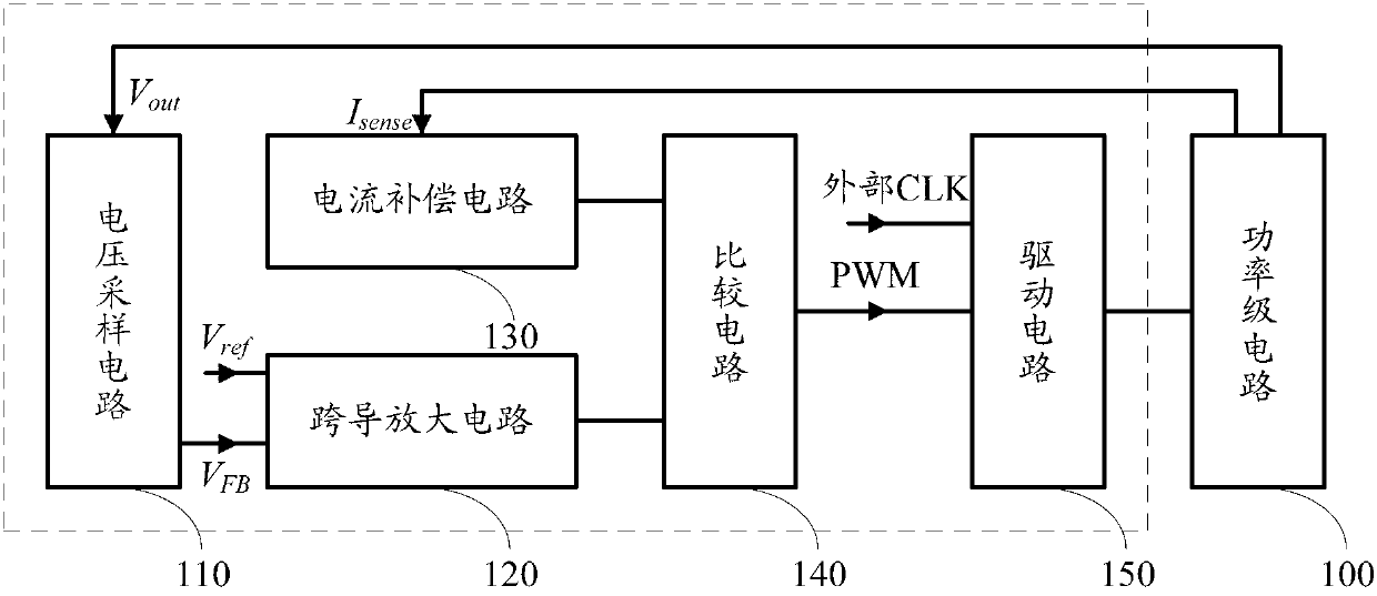
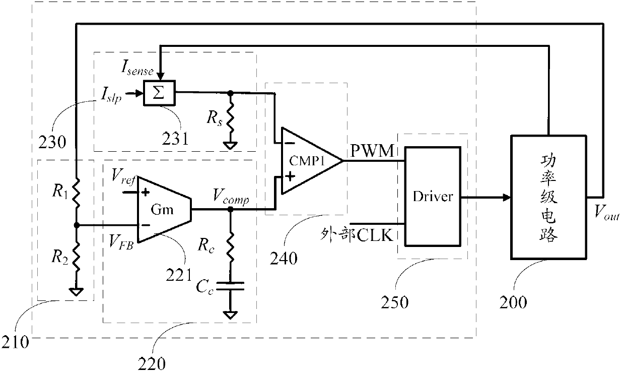
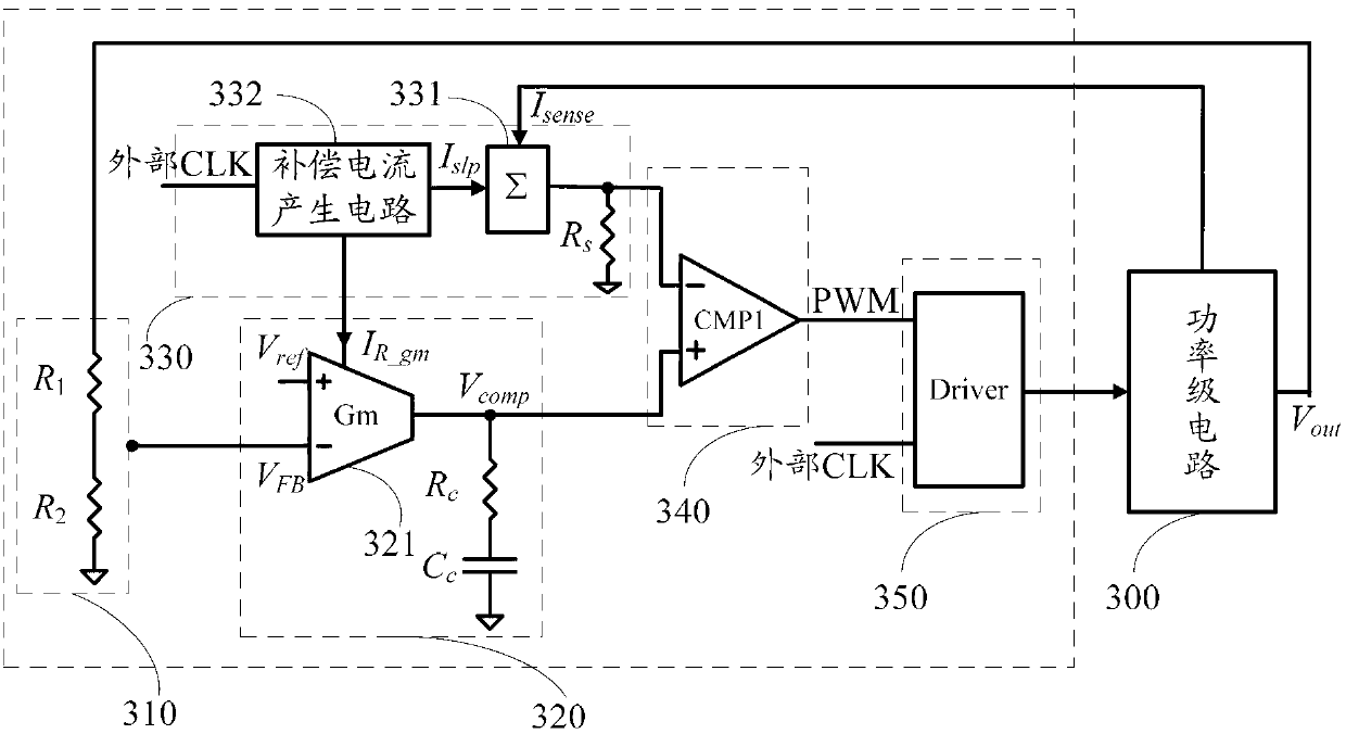
The invention discloses a slope compensation and loop bandwidth self-adaptation control circuit which is used for controlling a power-level circuit controlled by an electric current mode. The slope compensation and loop bandwidth self-adaptation control circuit comprises a voltage sampling circuit, a transconductance amplifying circuit, a current compensation circuit, a comparison circuit and a driving circuit, wherein the voltage sampling circuit is used for acquiring a feedback voltage which is used for representing an output voltage, the transconductance amplifying circuit is used for generating a voltage compensation signal according to the feedback voltage and a preset reference voltage, the current compensation circuit is used for generating a slope compensation signal according to a compensation current which changes along with switching frequency change and a sampling current used for presenting the inductive current value of the power-level circuit, the comparison circuit is used for generating a PWM control signal according to the voltage compensation signal and the slope compensation signal, and the driving circuit is used for driving the power-level circuit according to an external clock signal and the PWM control signal. According to the slope compensation and loop bandwidth self-adaptation control circuit, self-adaptation control of slope compensation and loop bandwidth is achieved, and the requirements of a switching power supply for good stability and fast dynamic response under the condition of different switching frequencies are met. The invention further discloses a switching power supply using the slope compensation and loop bandwidth self-adaptation control circuit.

Description

technical field [0001] The present application relates to the technical field of switching power supply control, in particular to a slope compensation and loop bandwidth adaptive control circuit and a switching power supply using the same. Background technique [0002] In the design of switching power supplies, especially communication power supplies, the requirements for switching frequency are relatively high. For the convenience of users, currently designed switching power supply chips will have dedicated pins for connecting external clock signals, which is convenient for users to set external clock signals according to actual applications. clock signal. When the external clock signal is set, the switching frequency is determined. The size of the switching frequency will affect the stability and dynamic characteristics of the internal control loop of the chip, and then affect the performance of the switching power supply. In particular, for switching converters using cu...

Claims


Application Information

Patent Timeline
Patent Type & Authority Applications(China)
IPC IPC(8): G05F1/56
Inventor 武传欣
Owner SILERGY SEMICON TECH (HANGZHOU) CO LTD
Learn More