Gripping mechanical fingers with specific motion trajectory

A technology of movement trajectory and mechanical fingers, which is applied in the field of manufacturing, can solve the problems of complex structure and single movement of mechanical fingers, and achieve the effect of simple structure, simple operation and simple mechanism structure

Active Publication Date: 2015-11-04
ZHANGZHOU JIALONG TECH INC
View PDF6 Cites 0 Cited by
  • Summary
  • Abstract
  • Description
  • Claims
  • Application Information

AI Technical Summary

Problems solved by technology

[0003] The purpose of the present invention is to provide a clamping mechanical finger with a specific motion trajectory, which helps to solve the current problems of complex structure and single movement of the mechanical finger

Method used


Image

  • Gripping mechanical fingers with specific motion trajectory
  • Gripping mechanical fingers with specific motion trajectory
  • Gripping mechanical fingers with specific motion trajectory

Examples


Embodiment Construction

[0014] In order to make the above-mentioned features and advantages of the present invention more comprehensible, the following specific embodiments are described in detail with reference to the accompanying drawings.

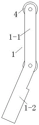
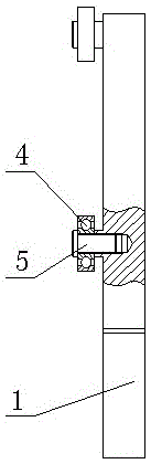
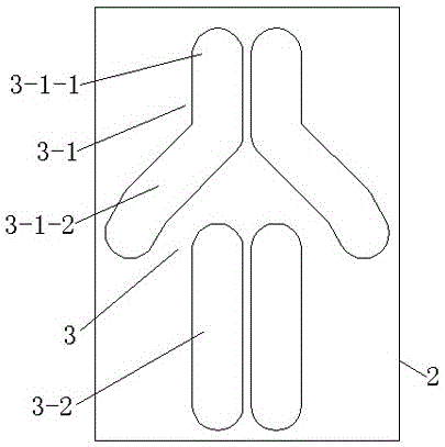
[0015] refer to Figure 1 to Figure 5 , the present invention relates to a clamping mechanical finger with a specific movement trajectory, including at least one pair of clamping plates 1 for clamping materials and a bottom plate 2 for installing the clamping plates 1, and at least one pair of symmetrical The set of guide grooves 3 is arranged. The guide groove group 3 is composed of two independent upper guide grooves 3-1 and lower guide grooves 3-2. The splint 1 is composed of the upper longitudinal section 1-1 and the lower Clamping section 1-2, the upper and lower parts of the longitudinal section 1-1 of the splint are respectively provided with rollers 4 installed in the upper guide groove 3-1 and the lower guide groove 3-2, so as to realize rolling connec...


PUM


Abstract

The invention relates to a clamping mechanical finger with special movement tracks. The clamping mechanical finger comprises at least one pair of clamping plates and a bottom plate, wherein the clamping plates are used for clamping material, the bottom plate is used for installing the clamping plates, the bottom plate is provided with at least one pair of symmetrical guide groove groups, each guide groove group consists of an upper guide groove and a lower guide groove which are independently arranged, each clamping plate consists of an upper longitudinal section and a lower clamping section, the upper and lower parts of the longitudinal section of each clamping plate are respectively provided with a roller which is arranged in each upper guide groove and each lower guide groove to realize rolling connection, the clamping sections of the pair of clamping plates are in a splayed shape, the upper guide grooves of one pair of guide groove groups are also in the splayed shape, and the clamping sections can favorably form the opening and closing states. The clamping mechanical finger has the advantages that the structure is simple and compact, and the operation is simple, quick and reliable; by changing the shapes of the guide grooves, the movement tracks of the clamping mechanical finger can be changed, and the adapting capability for different working requirements is high; and by changing the shapes of the tail ends of the guide grooves, the stress condition during the clamping of the mechanical finger is realized, and the functions, such as self-locking, are realized.

Description

technical field [0001] The invention relates to a clamping mechanical finger with a specific motion trajectory, which belongs to the field of manufacturing. Background technique [0002] At present, most of the mechanical fingers are directly controlled by rotating or sliding pairs, which can only realize simple rotation or linear motion; or are controlled by multiple sets of independently controlled rotating or sliding pairs, which can realize special trajectory movements, but the structure and control system more complicated. Therefore, it is the object of the present invention to study the above problems. Contents of the invention [0003] The object of the present invention is to provide a clamping mechanical finger with a specific motion track, which helps to solve the problems of complicated structure and single movement of the current mechanical finger. [0004] Technical scheme of the present invention is: [0005] A clamping mechanical finger with a specific mo...

Claims


Application Information

Patent Timeline
Patent Type & Authority Patents(China)
IPC IPC(8): B25J15/08
Inventor 曾艺宾何燕婷
Owner ZHANGZHOU JIALONG TECH INC
Why Eureka
Try Eureka