
Storage equipment used in alumina industry

A technology for storage equipment and alumina, which is applied in the direction of containers, packaging, transportation and packaging, etc. It can solve the problems of the impeller of the easily damaged discharge pump and the wear of the bottom plate of the storage equipment, so as to ensure safe use and improve the service life.

Active Publication Date: 2013-09-25
SHENYANG ALUMINIUM MAGNESIUM INSTITUTE
View PDF3 Cites 2 Cited by
  • Summary
  • Abstract
  • Description
  • Claims
  • Application Information

AI Technical Summary

Problems solved by technology

[0004] The purpose of the present invention is to provide a slurry storage device for the alumina industry, which solves the problems of the bottom plate of the storage device in the prior art, and the impeller of the discharge pump is easily damaged. The structure is simple and reasonable, and the use of the device can be extended. life, can protect associated equipment

Method used


Image

  • Storage equipment used in alumina industry
  • Storage equipment used in alumina industry

Examples


Embodiment Construction

[0022] The present invention will be described in further detail below in conjunction with the accompanying drawings, but the protection scope of the present invention is not limited by the embodiments.

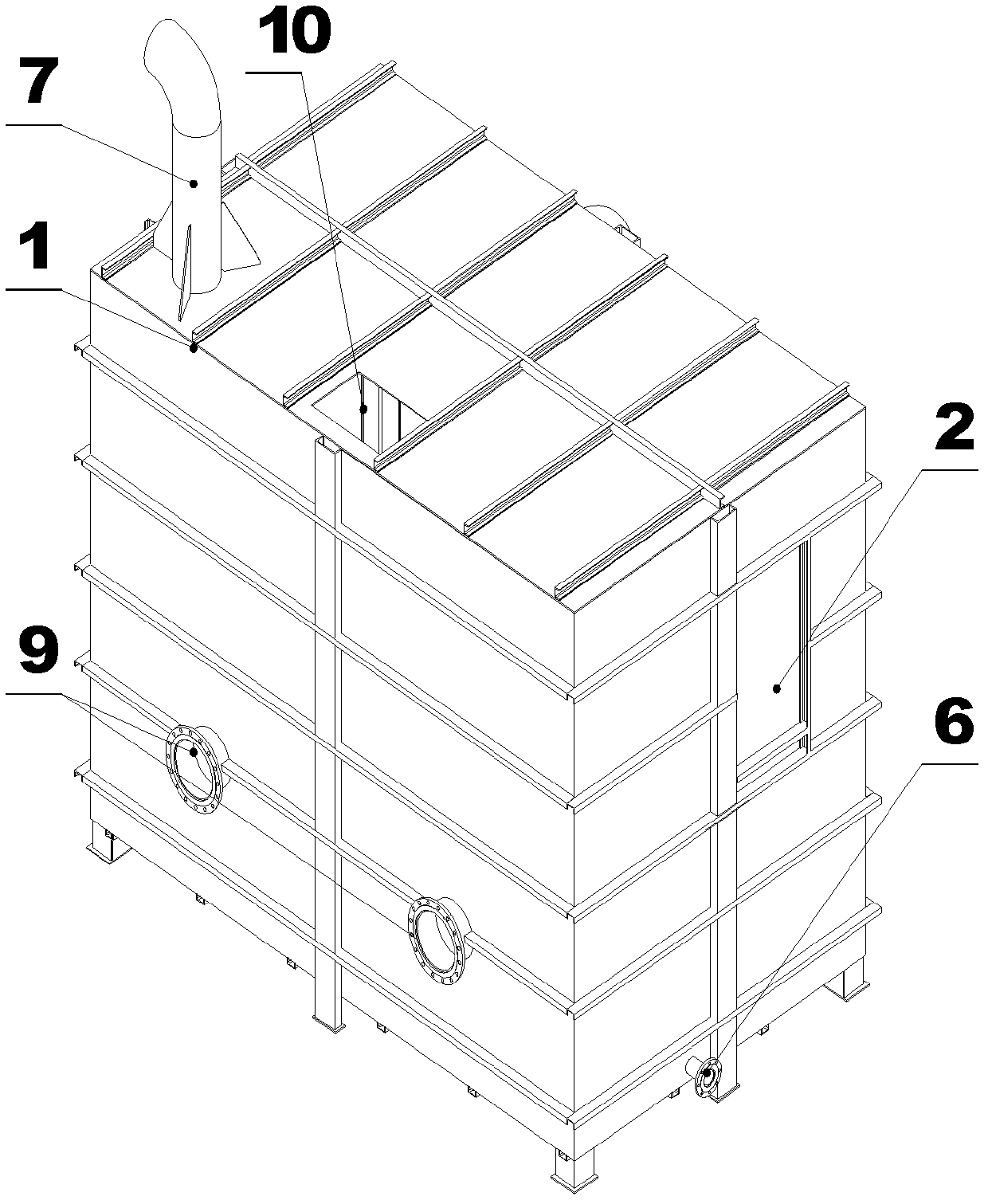
[0023] Such as Figure 1-2 As shown, the slurry storage equipment of the present invention mainly includes: tank body 1, feed inlet 2, material guide chute 3, anti-shock cone 4, bottom angle inclined plate 5, discharge port 6, vent hole 7, overflow Port 8, discharge port 9, observation hole 10 and grid screen 11, etc., the specific structure is as follows:

[0024] The tank body 1 of the storage equipment is fixed on the foundation; the feed port 2 is set on the middle and upper part of the side of the tank body 1. If the feed port 2 is double-opened, it needs to be opened symmetrically, and the slurry can form convection to avoid local accumulation and scarring; The material guide chute 3 in the tank body 1 is horizontally inclined downward to have a certain slope (10-80°),...


PUM


Abstract

The invention relates to the field of alumina production, in particular to slurry storage equipment used in the alumina industry, solves the problems that the baseplate of conventional storage equipment is susceptible to abrasion and the impeller of a discharging pump is susceptible to damage, and can prolong the service life of the storage equipment which is simple in structure and protect associated equipment. According to the storage equipment, guide skewed slots tilting down are formed in a tank body; the higher ends of the guide skewed slots are connected with a feed opening; the lower parts of the lower end outlets of the guide skewed slots correspond to anti-impact cones; the anti-impact cones are arranged at the bottom in the tank body and fixed on the baseplate of the tank body; slurry down from the guide skewed slots can flow onto the anti-impact cones, so that the slurry are prevented form impacting the baseplate of the tank body when flowing down. The discharge openings I of the storage equipment are formed in the bottom of the tank body and are higher than an emptying opening; meanwhile, screen stencils are arranged at the discharge openings II of the inner wall of the tank body. Thus, the steel balls, which become smaller due to abrasion, cannot flow out along with the slurry through the discharge openings I, so that the safe use of the discharging pump is ensured.

Description

technical field [0001] The invention relates to the field of alumina production, in particular to a slurry storage device used in the alumina industry. Background technique [0002] In the production of alumina, the slurry ground by the ball mill contains a large amount of silt and impurities. When the slurry enters the storage equipment, it will produce impact and wear the bottom plate of the storage equipment, thereby affecting the service life of the storage equipment. [0003] In addition, the steel balls in the ball mill will become smaller after a long time of use. When they are small enough, the steel balls will easily flow into the storage tank with the slurry, and when they flow through the discharge pump through the discharge port, they will Damage the impeller of the discharge pump, and eventually damage the blades of the pump. Therefore, a storage device with a new structure is needed to solve the above problems. Contents of the invention [0004] The purpos...

Claims


Application Information

Patent Timeline
IPC IPC(8): B65D88/54B65D90/22B65D90/00
Inventor 胡克荣
Owner SHENYANG ALUMINIUM MAGNESIUM INSTITUTE
Learn More