
Tool constant velocity device

A technology of constant velocity device and cutting tool, applied in the direction of driving device, manufacturing tool, metal processing mechanical parts, etc., can solve the problems of difficult to guarantee machining accuracy, complex transmission error of transmission mechanism, etc., to eliminate low-frequency vibration, less transmission error, motion smooth effect

Active Publication Date: 2015-09-30
CHANGCHUN INST OF OPTICS FINE MECHANICS & PHYSICS CHINESE ACAD OF SCI
View PDF3 Cites 0 Cited by
  • Summary
  • Abstract
  • Description
  • Claims
  • Application Information

AI Technical Summary

Problems solved by technology

[0004] The purpose of the present invention is to propose a tool constant velocity mechanism and a tool constant velocity device to solve the problems of difficulty in ensuring machining accuracy and many transmission errors caused by complex transmission mechanisms in the grating marking process of the prior art, and to realize gratings of different widths. scratch

Method used


Image

  • Tool constant velocity device
  • Tool constant velocity device
  • Tool constant velocity device

Examples


Embodiment Construction

[0021] The present invention will be further described below in conjunction with the accompanying drawings.

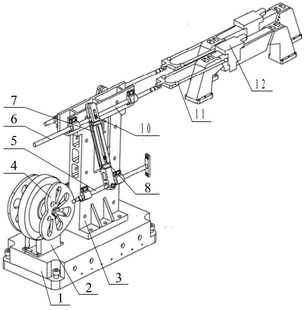
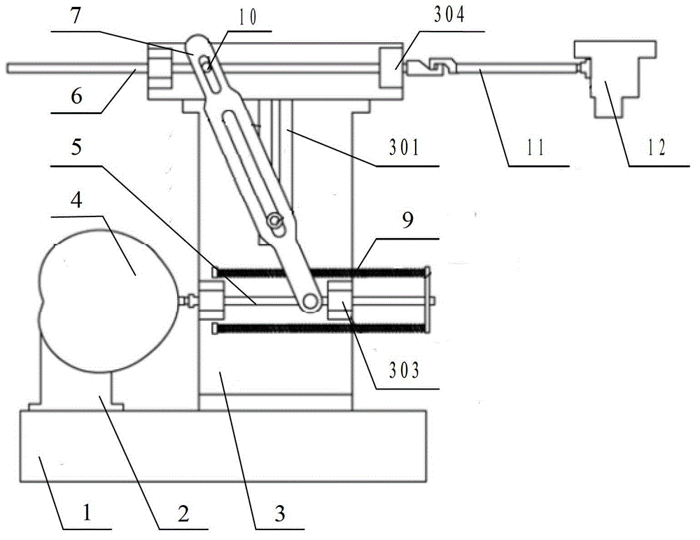
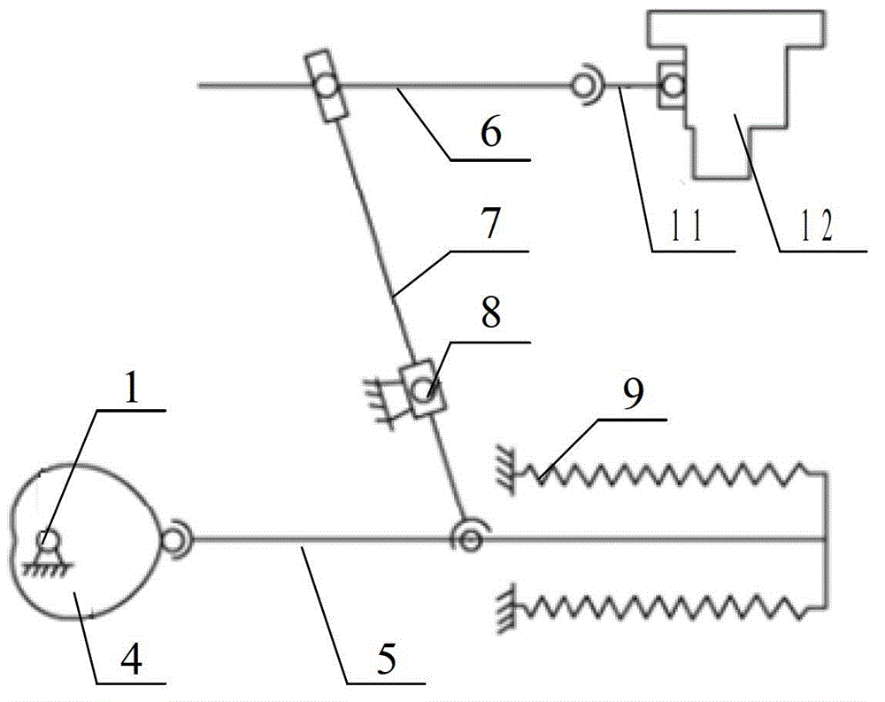
[0022] See attached figure 1 , attached figure 2 , attached image 3 And attached Figure 4 , The tool constant velocity device of the present invention comprises two sets of tool constant velocity mechanisms, a base 1, a first mounting frame 2 and a second mounting frame 3; the tool constant velocity mechanism comprises a constant velocity cam 4, a first push rod 5, The second push rod 6, the swing rod 7 and the adjustment knob 8; the first push rod 5 is connected with the constant velocity cam 4, and can reciprocate under the drive of the constant velocity cam 4, and the swing rod 7 One end is connected to the first push rod 5, and the other end is connected to the second push rod 6. There is a chute A705 in the middle of the swing rod 7, and a T-shaped mounting groove is provided on the second mounting frame 3. The mounting seat 301 of 302 is provided with two ...


PUM


Abstract

The invention discloses a cutter constant-speed device and belongs to the technical field of grating ruling machinery. The cutter constant-speed device aims at solving the problem that processing accuracy is difficult to ensure in the existing grating ruling process and lots of transmission errors can be caused due to a complex transmission mechanism and can achieve grating ruling with different widths. The cutter constant-speed device comprises two cutter constant-speed mechanisms which are separately arranged on two opposite surfaces of a substrate, the cutter constant-speed mechanisms can move in a reciprocating mode under the driving of constant-speed cams, one end of a swinging rod is connected with a first push rod, the other end of the swinging rod is connected with a second push rod, the swinging rod can swing in a reciprocating mode under the driving of the first push rod, the relative position of an adjusting knob on the swinging rod can be changed, and the moving distance specific value of the first push rod and the second push rod can be changed by changing the position of the adjusting knob on the swinging rod. The cutter constant-speed device ensures constant-speed motion of a scribing cutter bridge, can conveniently adjust moving distance of a scribing cutter by adjusting the position of the knob on the swinging rod and does not need to change the structure of the cutter constant-speed mechanisms and replace elements.

Description

technical field [0001] The invention belongs to the field of grating marking machines, in particular to a tool constant velocity device capable of adjusting the marking width of the grating in the grating marking machine. Background technique [0002] The grating is engraved by mechanical methods. At present, two methods are mainly used: intermittent engraving and continuous engraving; when engraving large gratings, continuous engraving is generally used, that is, the indexing system drives the grating blank to move continuously, and the engraving system drives the cutting tool. Carry out scoring, and at this time, the tool movement speed is required to be constant during the scoring process. [0003] "Instrument Technology and Sensors" 1984, "A Brief Introduction to Large-scale Grating Scribing Machines in the United States" pointed out that the existing constant-velocity marking system mainly uses the curve correction plate to correct the speed of the crank double pendulum...

Claims


Application Information

Patent Timeline
Patent Type & Authority Patents(China)
IPC IPC(8): B23Q5/027
Inventor 唐玉国陈科位巴音贺希格齐向东冯树龙
Owner CHANGCHUN INST OF OPTICS FINE MECHANICS & PHYSICS CHINESE ACAD OF SCI
Learn More