
Infrared Stereo Thermal Imaging Scanning System

A scanning system and thermal imaging technology, applied in the physical field, can solve the problems of sensor aging, fault impact detection, and high probability of detection error of infrared thermal imaging cameras, etc., and achieve the effect of improving detection speed and accuracy

Active Publication Date: 2014-10-08
麦柯尔智能科技(苏州)有限公司
View PDF8 Cites 3 Cited by
  • Summary
  • Abstract
  • Description
  • Claims
  • Application Information

AI Technical Summary

Problems solved by technology

[0003] The object of the present invention is to provide an infrared stereoscopic thermal imaging scanning system. The infrared stereoscopic thermal imaging scanning system needs to solve the problem that the infrared thermal imaging camera used to detect the temperature of the human body surface in the prior art has a large detection error probability and a sensor Technical issues of aging and fault impact detection

Method used


Image

  • Infrared Stereo Thermal Imaging Scanning System
  • Infrared Stereo Thermal Imaging Scanning System

Examples


Embodiment 1

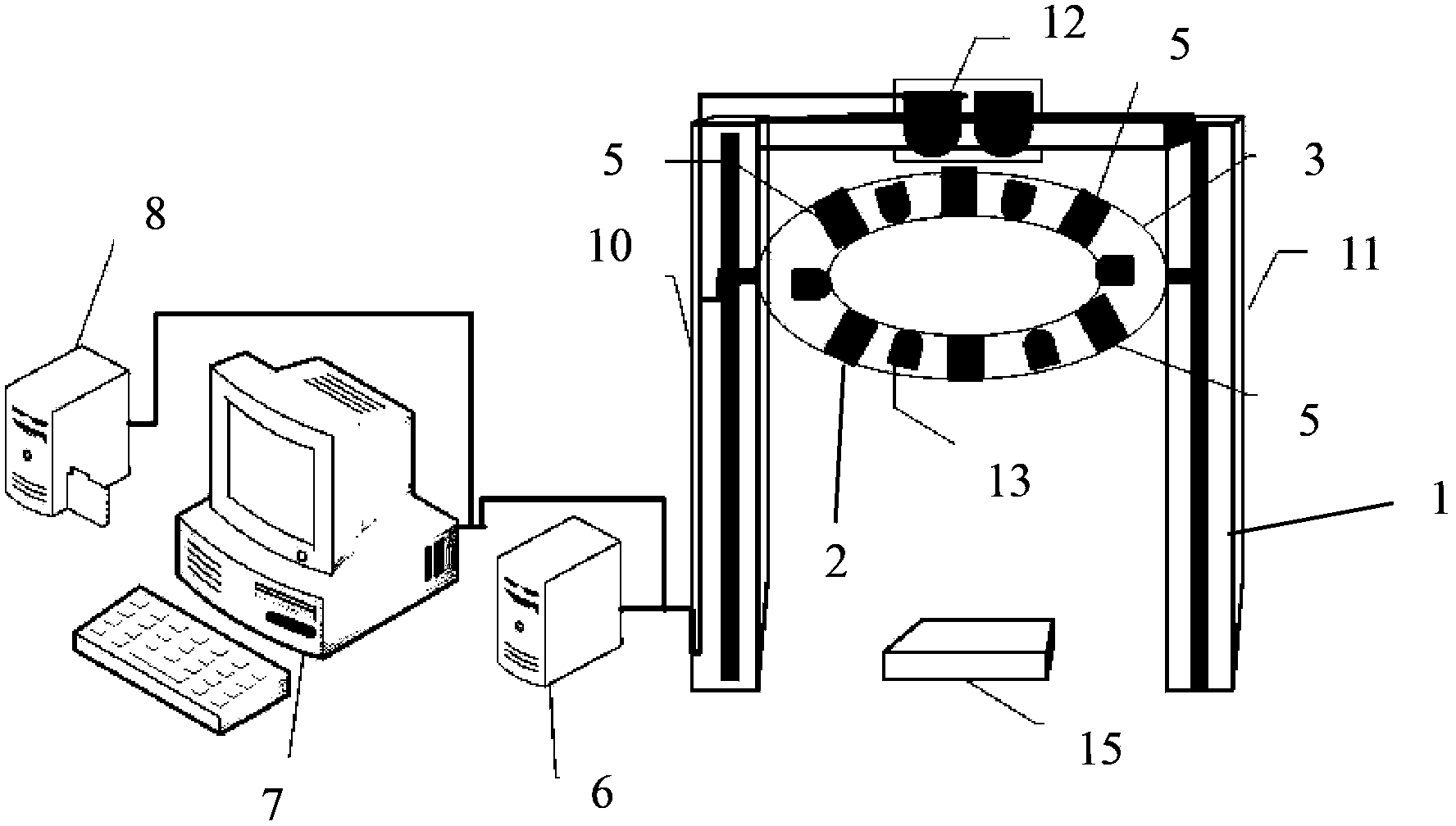
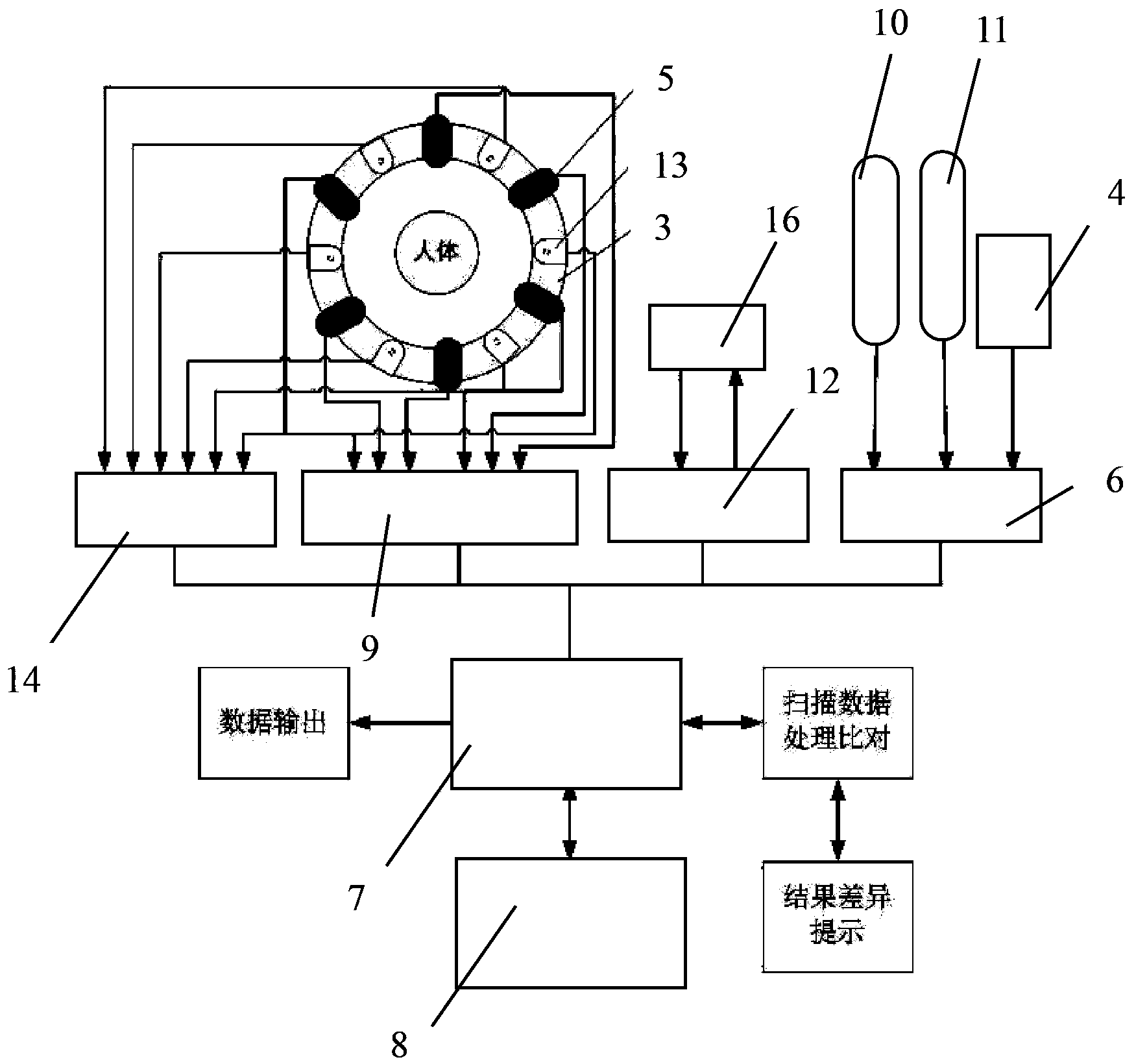
[0019] Such as figure 1 and figure 2 As shown, the infrared stereoscopic thermal imaging scanning system of the present invention includes an upright support 1, wherein a lifter is arranged on the upright support 1, and an annular support 2 is connected to the lifter. A rotating ring 3 is arranged on the ring support 2, and a circumferential driving mechanism 4 is arranged between the rotating ring 3 and the ring support 2. The radial direction of the rotating ring 3 is perpendicular to the moving direction of the lifter. There are at least two infrared thermal imaging sensors 5, any one of the infrared thermal imaging sensors 5 is connected to a data acquisition device 9 through a signal line, the lifter includes a vertical direction drive device, and the circumferential drive mechanism 4 and the control ends of the vertical direction driving device are respectively connected to a controller 6 .

[0020] Further, the data collection device 9 is set in a computer 7 .

[00...


PUM


Abstract

An infrared three-dimensional thermal imaging scanning system comprises an erect support. A lifter is disposed on the erect support. An annular support is connected to the lifter. A rotating ring is disposed on the annular support. A circumferential-direction drive mechanism is disposed between the rotating ring and the annular support. At least two infrared thermal imaging sensors are arranged on the rotating ring. Each optional infrared thermal imaging sensor is connected with a data acquisition device through a signal line. A temperature calibrator is disposed at the top of the erect support. Infrared transmitters are disposed on the rotating ring. The infrared three-dimensional thermal imaging scanning system has the advantages that at least two infrared thermal imaging sensors and infrared transmitters are disposed on the periphery of a to-be-scanned object serving as a central point, the lifter and the rotating ring are used to control the infrared thermal imaging sensors to move up and down and rotate on a plane, scanning of a to-be-scanned human body is achieved without movement of the human body, scanning accuracy and speed are increased greatly, and infrared thermal imaging sensors failed in updating can be discovered timely.

Description

Technical field: [0001] The invention relates to the field of physics, in particular to thermal imaging technology, in particular to an infrared stereoscopic thermal imaging scanning system. Background technique: [0002] Infrared thermal imaging technology has been applied in the medical field. As disclosed in the CN100502767C Chinese Patent Announcement, using an infrared thermal imager to record and display the temperature distribution of the human body surface, combined with changes in human anatomical structure, tissue metabolism, blood circulation and nerve status, can help diagnose diseases. In the prior art, the infrared thermal imaging camera used to detect the body surface temperature of the human body is equipped with only one infrared thermal imaging sensor. During the detection, the human body performs multiple rotations according to the needs, and due to the rotation of the soles of the human body, conditioned reflex occurs. This leads to local changes in the ...

Claims


Application Information

Patent Timeline
Patent Type & Authority Patents(China)
IPC IPC(8): A61B5/01
Inventor 葛晓松
Owner 麦柯尔智能科技(苏州)有限公司
Learn More