
Part recognition system and part recognition method

An identification method and part technology, applied in the direction of electrical components, electrical components, assembling printed circuits with electrical components, etc., can solve problems such as the inability to judge the difference in the relative position of the pins

Active Publication Date: 2013-09-18
GIGA BYTE TECH CO LTD
View PDF3 Cites 6 Cited by
  • Summary
  • Abstract
  • Description
  • Claims
  • Application Information

AI Technical Summary

Problems solved by technology

Although the automation device can quickly place the parts on the circuit board, after the automation device picks up the plug-in parts, it cannot judge the difference between the relative position of the pin and the relative position of the jack

Method used


Image

  • Part recognition system and part recognition method
  • Part recognition system and part recognition method
  • Part recognition system and part recognition method

Examples


Embodiment Construction

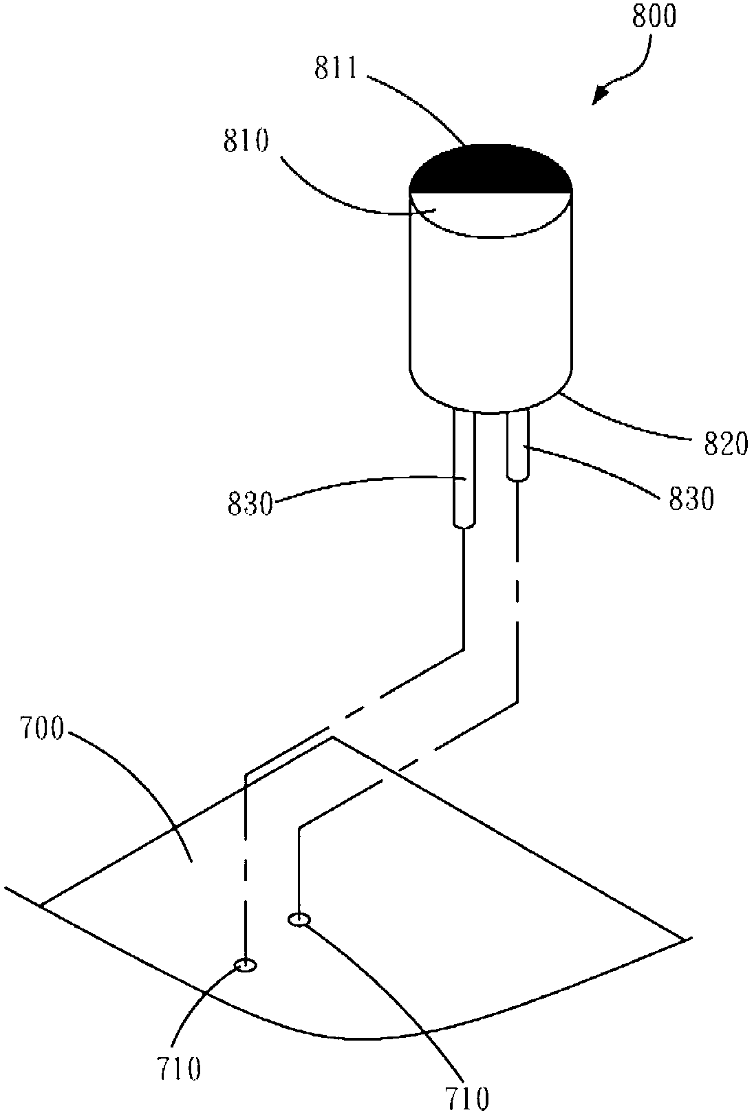
[0045] see figure 1 As shown, the part recognition system disclosed in the first embodiment of the present invention is used to generate an instruction to drive an automatic device 900 to adjust the part 800 after picking up (Pick-up) a part 800 (insertion-part). pin 830 to a predetermined position, and place the component 800 on a printed circuit board 700 .

[0046] refer to figure 2 As shown, the component 800 includes a top 810 , a bottom 820 and at least one set of pins 830 disposed on the bottom 820 . The top 810 of the part 800 includes at least one positioning feature 811 . The printed circuit board 700 includes sockets 710 for inserting corresponding pins 830 . The automation device 900 picks up the part 800 and installs the part 800 on the printed circuit board 700 so that each pin 830 is inserted into the corresponding socket 710 .

[0047] Such as figure 1 The illustrated automation device 900 includes a picking unit 910 for picking up the part 800 . The pic...


PUM


Abstract

The invention relates to a part recognition system for driving an automatic device to pick up a part and adjust the pin of the part to a preset position, wherein the part comprises a top portion, a bottom portion and at least one set of pins, wherein the pins are arranged on the bottom portion and the top portion comprises at least one positioning characteristic. The part recognition system comprises a material conveying device, an optical sensor and a data processing device, wherein the material conveying device adjusts the part to a preset placing state for the automatic device to pick up, the optical sensor is arranged at one side of the material conveying device and acquires sampling data from the top of the part at a preset placing state and the data processing device electrically connects the optical sensor and the automatic device. The data processing device receives the sampling data, generates an instruction according to the positioning characteristic, sends the instruction to the automatic device and rotates the part according to the instruction after the automatic device is driven to pick up the part.

Description

【Technical field】 [0001] The invention relates to an automatic assembly of parts, in particular to a part identification system and a part identification method. 【Background technique】 [0002] When making a circuit board, such as a computer motherboard, many electronic parts must be placed on a printed circuit board (PCB) one by one and soldered. The aforementioned electronic components include at least two pins. For example, in addition to the cylindrical body, the capacitor also includes two prongs, and the two prongs have positive and negative poles respectively. The PCB substrate includes pre-set sockets corresponding to the two pins respectively. The two prongs must be inserted into the correct jack according to the positive and negative poles before welding can be performed. [0003] The operation of placing the aforementioned electronic components on the substrate and inserting the pins into the correct sockets is currently mainly done manually. Although the auto...

Claims


Application Information

Patent Timeline
IPC IPC(8): H05K13/08H05K13/04H05K3/30G01B11/00
Inventor 翁仁龙杨胜安林朝熙
Owner GIGA BYTE TECH CO LTD
Learn More