Header structure of electric cabinet

A technology of electrical cabinets and brows, applied in the field of electrical cabinets, can solve the problems of inability to change, troublesome installation, unclear identification, etc., and achieve the effect of beautiful appearance, reasonable layout, and simple demolition

Inactive Publication Date: 2013-09-18
SHANGHAI XINLAI IND
View PDF0 Cites 1 Cited by
  • Summary
  • Abstract
  • Description
  • Claims
  • Application Information

AI Technical Summary

Problems solved by technology

[0005] The purpose of the present invention is to overcome the deficiencies of the prior art, adopt a brow structure that is easy to install, and solve the problems of troublesome installation, unclear identification and inability to change

Method used


Image

  • Header structure of electric cabinet
  • Header structure of electric cabinet
  • Header structure of electric cabinet

Examples


Embodiment

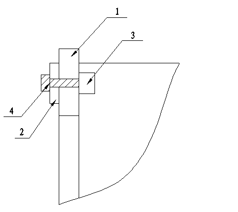
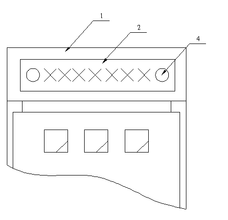
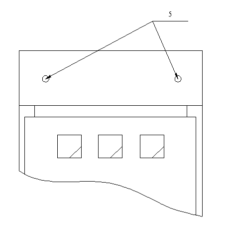
[0021] Such as figure 1 —— Figure 5 As shown, the present invention includes a cabinet body 1, a brow board 2, and also includes two magnets 3, two fixed plugs 4, two jacks 5 are provided at the brow position of the cabinet body 1, and one brow board 2 is respectively provided at both ends. The installation hole 6 and the jack 5 have the same size and position as the installation hole 6; the jack 5 is fixedly installed with a magnet 3 on one side of the cabinet 1, and the fixed plug 4 passes through the installation hole 6 of the brow plate 2 And the jack 5 is fixed on the magnet 3 by magnetic attraction; the fixed plug 4 is made of stainless iron material, and one end is a flat cylinder structure 41, and its diameter is slightly larger than the jack 5 and the mounting hole 6, and the other end of the fixed plug 4 It is a long cylindrical structure 42 whose diameter matches the socket 5 and the mounting hole 6 .

[0022] Another embodiment:

[0023] Such as Figure 6 —— ...


PUM


Abstract

The invention relates to an electric cabinet and particularly relates to a header structure of an electric cabinet. The header structure comprises a cabinet body and a header plate. The header structure is characterized in that the structure further comprises magnets and locking-type plugs; at least two jacks are formed in the header position of the cabinet body; an installation hole is formed in each of the two ends of the header plate; the jacks and the installation holes are identically sized and are positioned to match each other; the magnets are fixedly installed at the sides, located in the cabinet body, of the jacks; and the locking-type plugs are magnetically attracted and fixed on the magnets after passing through the installation holes and the jacks of the header plate. Compared with the prior art, the header structure is simple to install and remove, is reasonable in layout, is convenient to store, has beautiful appearance and can meet the requirement of each user for changing the function identifiers of the cabinet body.

Description

technical field [0001] The invention relates to an electric cabinet, in particular to a brow structure of the electric cabinet. Background technique [0002] The brow of the electrical cabinet is an identification plate installed on the top of the electrical cabinet to identify the model, type, specification, manufacturer and other information of the electrical cabinet. Existing electrical cabinet brows generally come in two forms: [0003] It is made of a section bar with a rectangular shape. There are connecting screw holes at the back of the brow and the front of the horizontal brow of the electrical cabinet, and are connected to the top of the electrical cabinet by screws or bolts. This kind of eyebrow installation is more troublesome, so it is generally installed on the electrical cabinet when it leaves the factory. The electrical cabinet with the brow installed is not easy to pack during transportation and storage, and it is also easy to damage. [0004] The oth...

Claims


Application Information

Patent Timeline
IPC IPC(8): H05K5/02
Inventor 赖真华
Owner SHANGHAI XINLAI IND
Why Eureka
Try Eureka