Electrode structure applied to dielectric liquid lens

A technology of electrode structure and substructure, applied in lens, optics, instrument, etc., can solve the problems of long displacement distance, long reaction time of dielectric liquid lens, slow deformation of liquid droplets, etc. The effect of increasing and decreasing reaction time

Active Publication Date: 2015-06-24
叶哲良
View PDF6 Cites 0 Cited by
  • Summary
  • Abstract
  • Description
  • Claims
  • Application Information

AI Technical Summary

Problems solved by technology

However, the deformation speed of the liquid beads driven by the concentric ring electrodes is too slow and the displacement distance is too long, which makes the response time of the dielectric liquid lens too long.

Method used


Image

  • Electrode structure applied to dielectric liquid lens
  • Electrode structure applied to dielectric liquid lens
  • Electrode structure applied to dielectric liquid lens

Examples


Embodiment Construction

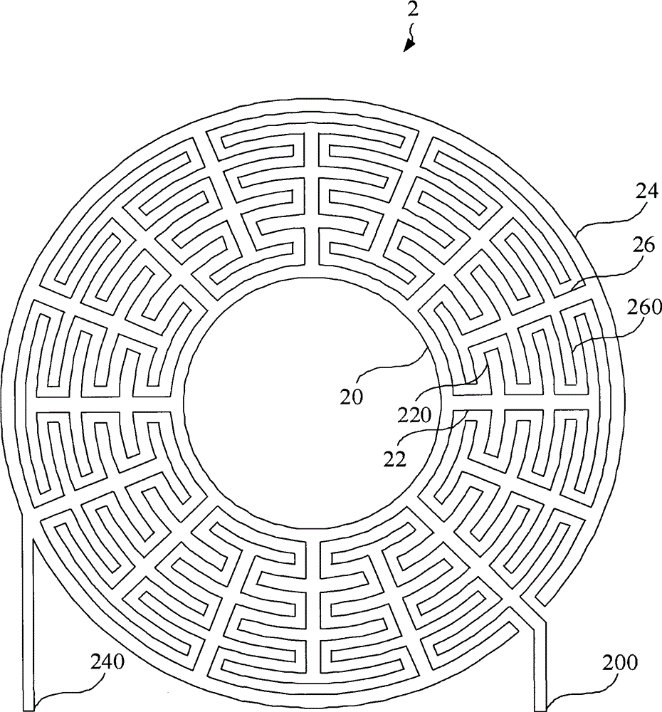
[0030] see figure 2 , figure 2 Shown is a schematic diagram of an electrode structure according to a preferred embodiment of the present invention. Such as figure 2 As shown, the present invention discloses an electrode structure 2, which is applied to a liquid lens. The electrode structure 2 includes: a first annular body 20, a plurality of first connecting parts 22, a second annular body 24 and a plurality of The second connection part 26 . A plurality of first connecting parts 22 are connected to the first annular body 20, and extend radially outward from the geometric center of the first annular body 20; a plurality of second connecting parts 26 are connected to the second annular body 24, and The geometric center of the second annular body 24 extends radially inward; meanwhile, the first annular body 20 and the second annular body 24 are on the same plane, and the geometric center of the first annular body 20 is in the same plane as the second annular body. The geo...


PUM


Abstract

The invention discloses an electrode structure applied to a dielectric liquid lens. The electrode structure comprises a first annular body, a number of first connecting parts which are connected with the first annular body and radially extend outward centring on the geometric center of the first annular body, a second annular body, and a number of second connecting parts which are connected with the second annular body and radially extend inward centring on the geometric center of the second annular body. The first annular body and the second annular body are in the same plane. The geometric center of the first annular body and the geometric center of the second annular body are at the same position. The first connecting parts and the second connecting parts are annularly arranged in a mutual staggered manner.

Description

technical field [0001] The present invention relates to an electrode structure, and in particular, the present invention relates to an electrode structure for a dielectric liquid lens. Background technique [0002] With the continuous advancement of technology, consumer electronic products are becoming more and more popular, and they are constantly developing towards lightweight and thinness. Among them, digital cameras used to record life and camera phones with communication functions are the most common. In general cameras, the quality of shooting results is often closely related to the zoom system. The traditional zoom system is generally composed of a lens group, a precise stepping motor and some mechanical structures. The motor stretches the lens back and forth, and then changes the distance between the lenses to achieve the purpose of zooming. However, this mechanical zoom system has a complex structure. And fragile, and need to occupy a considerable space, not conduc...

Claims


Application Information

Patent Timeline
Patent Type & Authority Patents(China)
IPC IPC(8): G02B3/14
Inventor 蔡智伟叶哲良
Owner 叶哲良
Why Eureka
Try Eureka