Pneumatic tire
A technology of pneumatic tires and tires, which is applied to tire parts, tire tread/tread pattern, transportation and packaging, etc., to achieve the effect of improving snow performance and drainage performance
Active Publication Date: 2013-09-18
SUMITOMO RUBBER IND LTD
View PDF7 Cites 12 Cited by
- Summary
- Abstract
- Description
- Claims
- Application Information
AI Technical Summary
Problems solved by technology
[0004] However, although the above-mentioned pneumatic tire can improve some snow performance, there is room for further improvement.
Method used
View moreImage
Smart ImageViewing Examples


Examples
Embodiment
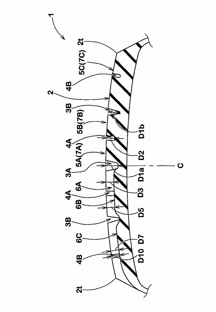
[0077] Manufacturing has figure 1 The performances of tires having the basic structure shown in Table 1 and the main grooves and lateral grooves shown in Table 1 were evaluated, and the common specifications are as follows.
[0078] Tire size: 195 / 65R15
[0079] Rim size: 15×6.5
[0080] Tread contact width TW: 152mm
Login to View More PUM
 Abstract
The invention provides a pneumatic tire, which can greatly improve performance on snow and draining performance. A tire face part (2) of the pneumatic tire (10) is provided with a central main channel (3A), a pair of tire shoulder main channels (3B), and a pair of central auxiliary channels (4A), and thereby an external side central land part (5B) and a tire shoulder land part (5C) are formed. The channel width (W1a) of the central main channel (3A) is larger than the channel width (W1b) of the tire shoulder main channels (3B). A tire shoulder transverse channel (6C) is disposed at the tire shoulder land part (5C). The angle (Alpha 7) of the tire shoulder transverse channel (6C) is larger than the angle (Alpha 4) of an outer side central transverse channel (6B). An outer end (6Bo) by which the outer side central transverse channel (6B) is communicated with the tire shoulder main channels (3B) and an inner end (6Ci) by which the tire shoulder transverse channel (6C) is communicated with the tire shoulder main channels (3B) are oppositely disposed with the tire shoulder main channel (3B) being arranged therebetween.
Description
technical field [0001] The present invention relates to a pneumatic tire capable of greatly improving on-snow performance and drainage performance. Background technique [0002] In the past, there have been proposed pneumatic tires in which blocks are arranged at intervals in the tire circumferential direction on the tread portion, wherein the blocks are divided by a plurality of main grooves extending in the tire circumferential direction and transverse grooves traversing between the main grooves (for example, , refer to the following patent document 1). In such a pneumatic tire, traction can be obtained by biting the blocks into the snowy road, so that the on-snow performance can be improved. [0003] Patent Document 1: Japanese Unexamined Patent Publication No. 2009-269500 [0004] However, although the above-mentioned pneumatic tire can partially improve the on-snow performance, there is room for further improvement. In addition, due to the influence of the greenhouse...
Claims
Login to View More Application Information
Patent Timeline
 Patent Type & Authority Applications(China)
IPC IPC(8): B60C11/03B60C11/11
CPCB60C2011/0344B60C11/01B60C11/04B60C11/11B60C11/13
Inventor 高桥伸吾
Owner SUMITOMO RUBBER IND LTD
Features
- R&D
- Intellectual Property
- Life Sciences
- Materials
- Tech Scout
- Unparalleled Data Quality
- Higher Quality Content
- 60% Fewer Hallucinations
Learn More Browse by: Latest US Patents, China's latest patents, Technical Efficacy Thesaurus, Application Domain, Technology Topic, Popular Technical Reports.
© 2025 PatSnap. All rights reserved.Legal|Privacy policy|Modern Slavery Act Transparency Statement|Sitemap|About US| Contact US: help@patsnap.com