coolant pump

A technology for coolant pumps and pump shafts, applied to pumps, pump devices, pump components, etc., can solve problems such as small structural space/installation volume

Inactive Publication Date: 2016-04-27
NIDEC GPM GMBH
View PDF16 Cites 0 Cited by
  • Summary
  • Abstract
  • Description
  • Claims
  • Application Information

AI Technical Summary

Problems solved by technology

[0030] Therefore, the object of the present invention is to develop an axial flow coolant pump for internal combustion engines mechanically driven by pulleys, gears, plug shafts etc. A technically smaller construction space / installation volume and the same, that is to say for the usual pump shaft speed of the coolant pump, allow a marked increase in the pump pressure in an axial coolant pump; and it is at the same time characterized by Significantly improved, stable characteristic curve for coolant volume flow at constant speed with respect to pump pressure compared to the prior art, additionally insensitivity to cavitation, avoids swirling of the delivered volume flow, while ensuring very high efficiency, additionally features Due to a very compact, technically simple to manufacture and assemble, cost-effective and robust design, and ensures high operational safety even with a very long service life for coolants subject to pollutant loads sex and reliability

Method used


Image

  • coolant pump

Examples


Embodiment Construction

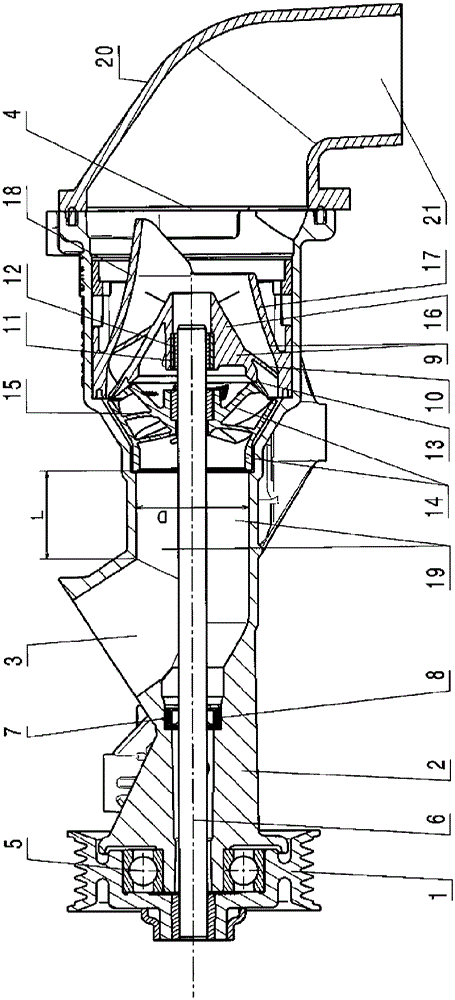
[0035] The axial flow coolant pump according to the present invention has: a pump housing 2; an inlet 3 arranged at the pump housing on the suction side and an outlet 4 arranged at the pump housing on the pressure side; The pump bearing 5 is rotatably supported in the pump housing 2 or at the pump shaft 6 connected to the pulley 1 in a rotationally fixed manner; on the drive side, beside the inflow port 3, in a seal seat 7 in the pump housing 2 A pump shaft seal 8 arranged between the seal seat 7 and the pump shaft 6; a guide wheel 9 with guide vanes 10 arranged in the pump housing 2 in a torsion-resistant manner, and a bearing receptacle is present in the guide wheel 9 11. A sliding bearing 12 is arranged therein, and the pump shaft 6 is supported in the sliding bearing 12 with its end of the pump shaft opposite to the driving side (for example, the pulley 1), wherein, on the pump shaft 6, at the inlet In the direction of 3, a running wheel 14 with blades 15 is arranged in an ...


PUM


Abstract

The invention relates to a coolant pump for an internal combustion engine in the form of an axial coolant pump mechanically driven by belt pulleys, gear wheels, plug shafts, etc. The object of the present invention is to develop an axial coolant pump for an internal combustion engine which, compared to the state of the art, requires a smaller installation space / installation volume and the same, that is to say for the usual pump shaft speed of the coolant pump. This case enables a marked increase of the pump pressure in axial coolant pumps; and it is at the same time characterized by a significantly improved, stable characteristic curve for the coolant volume flow with respect to the pump pressure for a constant rotational speed compared to the prior art, and moreover for the air Insensitivity to cavitation, avoids swirling of the delivery volume flow, while ensuring very high efficiency, is also characterized by a very compact, technically simple to manufacture and assemble, cost-effective and robust design, and even under coolant load High operating safety and reliability are also ensured with a very long service life in the presence of pollutant loads. The coolant pump according to the invention is characterized in that a semi-axial impeller with three-dimensionally curved blades (15), a Francis type or a diagonal flow impeller (14), is used as the impeller (14) and is arranged in the pump housing ( 2) The guide wheel (9) has an inner, tapering guide cone (16) in the flow direction and an outer conical guide cap (17) arranged at a distance therefrom, and both are symmetrical to each other Interconnected at intervals via three-dimensionally curved guide vanes (10), wherein the impeller (14) is spaced apart from the guide impeller (9) with an annular gap (13) such that the impeller (14) is not only at the end The sides are spaced apart from the adjacent outer edge of the guide cone (16) and at the end side from the adjacent outer edge of the guide cap (17).

Description

Technical field [0001] The invention relates to a coolant pump in the structure of an axial flow coolant pump which is mechanically driven by a pulley, a gear, a plug shaft and the like for an internal combustion engine. Background technique [0002] The prior art describes an axial flow coolant pump for an internal combustion engine. It is driven by the crankshaft of the internal combustion engine by means of an electric motor or also mechanically, for example via a pulley or the like. [0003] Therefore, in addition, the document US6056518A prescribes a coolant pump equipped with semi-axial wing wheels that is driven by a reluctance motor connected without passing through the shaft. Its semi-axial wing wheel driven by the motor is The outer periphery is supported in a pump housing with a middle inlet and a middle outlet. [0004] In the document DE10047387A1, the applicant also introduces an electrically driven, adjustable, and adjustable axial coolant pump with an axial impeller...

Claims


Application Information

Patent Timeline
IPC IPC(8): F04D1/04F04D13/02F04D29/12F04D29/44
CPCF04D1/04F04D13/021F04D29/126F04D29/448F04D13/02
Inventor A.施密特F.帕维莱克T.施泰纳S.比朔夫
Owner NIDEC GPM GMBH
Why Eureka
Try Eureka