
Electrical connector and cell

A technology for electrical connectors and batteries, which is applied in the direction of electrical components, battery pack components, circuits, etc., and can solve the problems of increased thickness of positive electrode tabs and negative electrode tabs, increased difficulty in welding electrical connectors, and battery rate performance. Damage and other problems, to achieve the effect of reasonable structure, avoid desoldering and virtual welding, and increase volume energy density

Inactive Publication Date: 2013-09-11
SHENZHEN BYD LITHIUM BATTERY
View PDF3 Cites 13 Cited by
  • Summary
  • Abstract
  • Description
  • Claims
  • Application Information

AI Technical Summary

Problems solved by technology

[0004] The purpose of the present invention is to solve the problem that the thickness of the positive electrode tab and the negative electrode tab of the existing battery is increased, which increases the difficulty of welding the electrical connection piece, easily causes the problems of desoldering and virtual welding, and leads to damage to the rate performance of the battery technical issues

Method used


Image

  • Electrical connector and cell
  • Electrical connector and cell
  • Electrical connector and cell

Examples

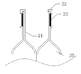
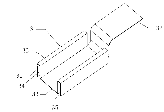
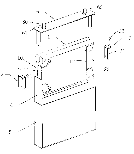

Embodiment Construction

[0024] In order to make the technical problems, technical solutions and beneficial effects solved by the present invention clearer, the present invention will be further described in detail below in conjunction with the accompanying drawings and embodiments. It should be understood that the specific embodiments described here are only used to explain the present invention, not to limit the present invention.

[0025] The electrical connector of the present invention is used to connect the wound pole core, which is known to those skilled in the art, see figure 1 , the winding pole core includes a coated area and an uncoated area, and the uncoated area forms an electrode lug. Specifically, the winding pole core of the present invention is formed by stacking a positive pole piece, a diaphragm and a negative pole piece in sequence and then winding them. The positive pole piece and the negative pole piece are respectively provided with a coated area and an uncoated area. The uncoa...


PUM

PropertyMeasurementUnit
thicknessaaaaaaaaaa

Abstract

The invention provides an electrical connector comprising at least two accommodating parts which are used to respectively accommodate at least two electrode pole ears of two curled pole cores which are adjacent; an extension which is used to connect to an electrode terminal on a cover plate; and an interconnecting piece which is used to connect the accommodating parts with the extension. The invention also provides a cell with the electrical connector. The electrical connector of the invention is reasonable in structure, and can be used for accommodating more than two curled pole cores via laser welding, so that the occupied space by the electrical connector is reduced, the welding difficulty of electrical connector to the curled pole cores and the cover plate is reduced, and unsoldering and pseudo soldering can be avoided. The electrical connector is beneficial for the integral structure setting of the cell, and enables the volume energy density of the cell to be increased.

Description

technical field [0001] The present invention relates to the battery field, and more specifically relates to an electrical connector and a battery. Background technique [0002] In recent years, with the development of battery technology, batteries are not only used as power sources for mobile communication devices such as mobile phones, notebook computers, and digital cameras, but also as power sources for robots, hybrid vehicles, and electric vehicles. High capacity. However, when the capacity of the battery is increased, it is necessary to make the winding pole core thicker. At the same time, in order to ensure the infiltration effect of the electrolyte, it is usually provided with a plurality of winding pole cores with a relatively small thickness. In this case, the positive electrode The electrode lug (the exposed part of the positive current collector) and the negative electrode lug (the exposed part of the negative current collector) are increased, and the overall thi...

Claims


Application Information

Patent Timeline
Patent Type & Authority Applications(China)
IPC IPC(8): H01M2/20H01M2/26B23K26/24
CPCY02E60/10
Inventor 何元元郑卫鑫
Owner SHENZHEN BYD LITHIUM BATTERY
Learn More