Negative refraction single-element polarization beam-splitting prism and polarization beam-splitting method

A beam-splitting prism and negative refraction technology, which is applied in the direction of polarizing elements, can solve the problems of composite prisms that consume large raw materials, low device laser damage resistance threshold, and general mechanical properties, and achieve high technical performance and reliability, anti-light High damage threshold, adjustable beam splitting angle and multiple effects

Inactive Publication Date: 2013-09-11
QUFU NORMAL UNIV
View PDF3 Cites 0 Cited by
  • Summary
  • Abstract
  • Description
  • Claims
  • Application Information

AI Technical Summary

Problems solved by technology

[0005] The Wollaston prism is composed of two crystals, which will cause the transmittance of the prism to be low. In the manufacturing process, the two crystals are glued together with an adhesive, so that the laser damage resistance threshold of the device is low, and the mechanical properties are average. It consumes a lot of raw materials, which is a fatal flaw for the utilization of natural crystals

Method used


Image

  • Negative refraction single-element polarization beam-splitting prism and polarization beam-splitting method
  • Negative refraction single-element polarization beam-splitting prism and polarization beam-splitting method

Examples


Embodiment 1

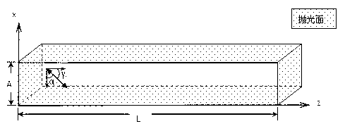
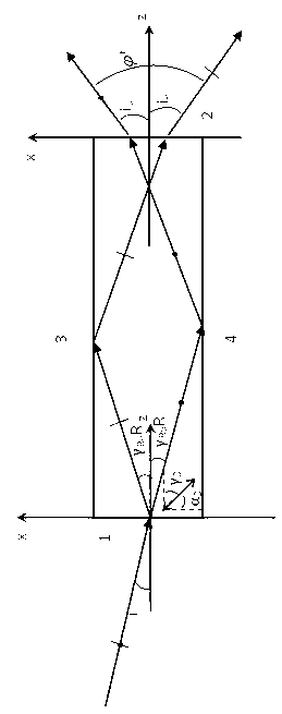
[0023] A polarizing beam splitting prism with a negative refraction unit. Its structure and splitting light path are as follows: figure 1 and 2 shown. The double arrows in the figure indicate the direction of the optical axis of the uniaxial birefringent crystal, and the cosine of the direction of the optical axis is (cosα 0 , cosγ 0 ). The design idea is as follows: unpolarized light enters the end face 1 of the prism at an incident angle i, and the light e is negatively refracted, and the refraction angle is γ Re , and then totally reflected by the interface 3 to the end face 2, and then by the refraction angle i e shoot. o The light is refracted at the end face 1, and is totally reflected to the end face 2 through the interface 4, at the refraction angle i o shoot.

[0024] Such as figure 1 The shown unit negative refraction polarizing beam splitter prism is made of a monolithic rectangular parallelepiped structure made of Iceland stone crystal. Reflector 3 and bo...

Embodiment 2

[0027] The similarities between this embodiment and Embodiment 1 will not be repeated, and the difference is that the crystal optical axis angle is 25 degrees, and the beam splitting angle is 15.87 degrees.

Embodiment 3

[0029] The similarities between this embodiment and Embodiment 1 will not be repeated, and the difference is that the crystal optical axis angle is 30 degrees, and the beam splitting angle is 18.39 degrees.


PUM

PropertyMeasurementUnit
Wavelengthaaaaaaaaaa

Abstract

Disclosed are a negative refraction single-element polarization beam-splitting prism and a polarization beam-splitting method. The negative refraction single-element polarization beam-splitting prism is composed of a single cuboid made of natural Iceland spar; an incidence end face, an emergence end face, a top reflecting surface and a bottom reflecting surface are polished surfaces; and the incidence end face is parallel to the emergence end face, and the top reflecting surface is parallel to the bottom reflecting surface. A light beam is transmitted to a single-element single-shaft birefringent crystal prism at a specific angle, o light is normally refracted on the incidence end face, fully reflected by the other side of the prism and emitted at a certain angle through refraction of the emergence end face after arriving at the emergence end face; and e light is negatively refracted on the incidence end face, fully reflected by the other side of the prism and emitted at a certain angle through refraction of the emergence end face after arriving at the emergence end face. The included angle formed by a crystal optical axis and an incidence interface is 45 degrees. The extinction ratio of the prism is superior to 10-5, and the natural transmittance in a spectrum area of 400-1600nm is 90%. The beam-spitting characteristics of the prism prove that the prism is provided with a plurality of functions of polarization beam-splitting, large beam-splitting angles and adjustability along with angles of incidence.

Description

technical field [0001] The invention discloses a conventional refraction of ordinary light (o light) in a uniaxial birefringent crystal prism, and negative refraction of extraordinary light (e light) through extraordinary refraction, and then the o and e light undergo total reflection and exit the crystal to produce The invention discloses a polarizing beam splitting method for large-angle beam splitting and a unit structure negative refraction polarizing beam splitting prism, belonging to the technical field of optical devices. Background technique [0002] Polarizing devices are important devices in the field of laser technology and polarization application technology, and polarizing beam splitting prisms are an important category of polarizing devices. Its research and development are of great significance to the development of modern optical technologies such as optical communication, optical information processing, optical testing, laser technology and optical computing...

Claims


Application Information

Patent Timeline
IPC IPC(8): G02B5/30
Inventor 吴闻迪
Owner QUFU NORMAL UNIV
Why Eureka
Try Eureka