
Measuring device and calibration method for optical lens distortion

A measuring device and optical lens technology, applied in the field of optical lens, can solve problems such as inaccurate correction effect and inability to obtain corrected images

Inactive Publication Date: 2013-09-11
SHANGHAI INST OF OPTICS & FINE MECHANICS CHINESE ACAD OF SCI
View PDF5 Cites 58 Cited by
  • Summary
  • Abstract
  • Description
  • Claims
  • Application Information

AI Technical Summary

Problems solved by technology

This correction method does not perform distortion correction on every point of the image, the correction effect is not very accurate, and the corrected image that fully meets the requirements cannot be obtained.

Method used


Image

  • Measuring device and calibration method for optical lens distortion
  • Measuring device and calibration method for optical lens distortion
  • Measuring device and calibration method for optical lens distortion

Examples


Embodiment Construction

[0036] The present invention will be described in further detail below in conjunction with the accompanying drawings and embodiments, but the protection scope of the present invention should not be limited thereby.

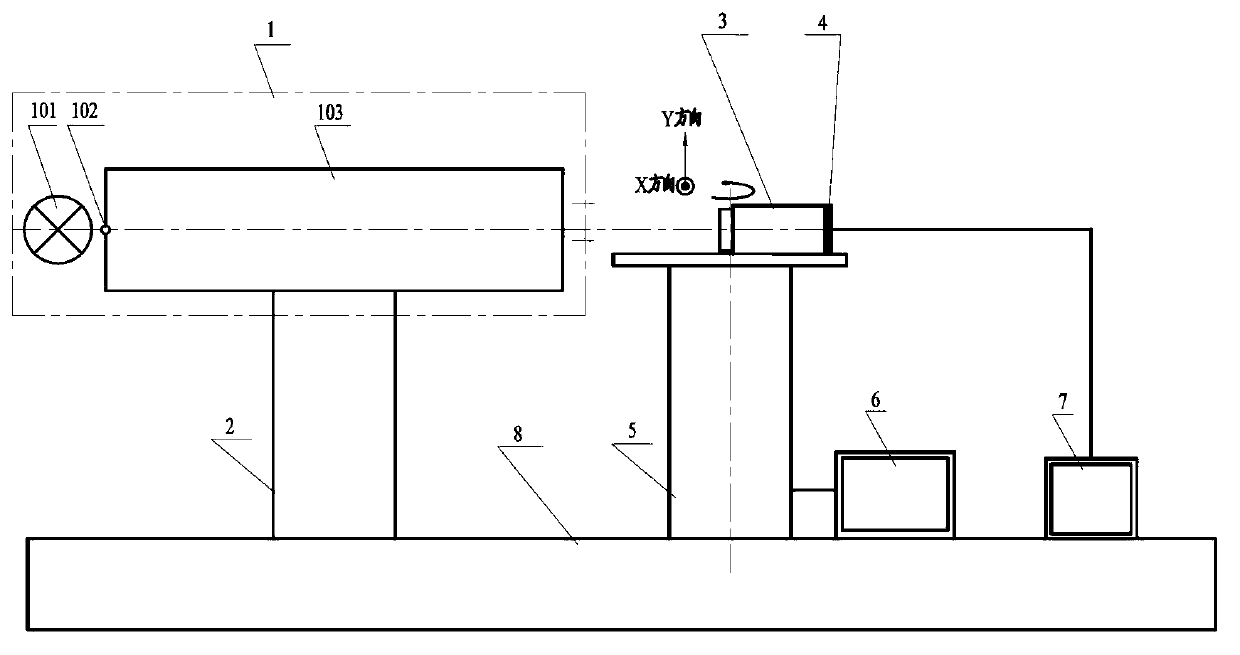
[0037] see first figure 1 , figure 1 It is a structural schematic diagram of the lens distortion measuring device to be tested in the present invention. It can be seen from the figure that the optical lens distortion measuring device of the present invention comprises a single starlight simulator 1, an adjustment frame 2, a lens to be tested 3, a CCD camera 4, a one-dimensional air bearing turntable 5, an angle encoder 6, a computer 7 and an optical The platform is composed of 8, and the positional relationship of the above components is as follows:

[0038] The adjustment frame 2 and the one-dimensional air-floating turntable 5 are placed on the optical platform 8, and the single star simulator 1 is composed of an integrating sphere light source 101, a collimat...


PUM


Abstract

Provided is a measuring device and a calibration method for optical lens distortion. The measuring device comprises a single star light simulator, an adjusting rack, a to-be-tested lens, a CCD (charge coupled device) camera, a one-dimensional air flotation turntable, an angle encoder, a computer and an optical platform. The calibration method includes the steps of using a centroid localization algorithm to determine centroid position coordinates of a star point image when the to-be-tested lens is under different fields of view, establishing a calibration model for the to-be-tested lens distortion based on the distribution of the centroid position coordinates of the star point image under the entire field of view, and realizing the calibration of the distorted to-be-tested lens. The measuring device and the calibration method for the optical lens distortion has the advantages that the device is simple; the method is convenient; measurement accuracy is high; and the optical lens distortion can be easily measured and calibrated.

Description

technical field [0001] The invention relates to an optical lens, in particular to a measuring device and a correction method for optical lens distortion. technical background [0002] Generally, the optical lens will have a certain degree of distortion when imaging, and it is difficult to achieve the ideal lens imaging effect. The size of the distortion largely determines the imaging quality of the lens and the measurement accuracy of the system, which will cause the geometric position of the image to be distorted. The feature extraction and parameter calculation of the image bring difficulties, which affects the misjudgment of information, and even cannot clearly distinguish the imaged object. Therefore, the measurement and correction of distortion of optical lenses used in precision measurement systems is particularly important. [0003] Known technology [1] Wide-angle distortion test system and method, the application date is Chinese patent 01256866.X on December 11, 200...

Claims


Application Information

Patent Timeline
Patent Type & Authority Applications(China)
IPC IPC(8): G01M11/02
Inventor 杨宝喜李璟陈明肖艳芬朱菁黄惠杰
Owner SHANGHAI INST OF OPTICS & FINE MECHANICS CHINESE ACAD OF SCI
Learn More