
Particle damping vibration absorbing device

A particle damping and vibration absorber technology, which is applied in the field of damping and vibration reduction, can solve the problems of large damping effect, restricting particle damping technology, and restricting the application of particle damping technology, and achieves the effect of saving space, broadening the scope of application and simple structure.

Inactive Publication Date: 2015-03-11
NANJING UNIV OF AERONAUTICS & ASTRONAUTICS
View PDF4 Cites 2 Cited by
  • Summary
  • Abstract
  • Description
  • Claims
  • Application Information

AI Technical Summary

Problems solved by technology

The above application methods have achieved good vibration control effects, but due to the energy consumption characteristics of the particles themselves (through the friction and collision energy between particles and particles and the inner wall of the container), when the particle damper is in a relatively strong vibration ( When the vibration acceleration amplitude Aa>1g), the damping particles in it produce relative motion and friction (similar to fluid, called liquid state), thus producing a large damping effect
And when it is in the state of micro-vibration (vibration acceleration amplitude Aa<1g), the damping particles are still relative to the container, and its effect is equivalent to an additional mass (called solid state or solid state), at this time, the particle damper basically does not provide damping effect , this feature largely limits the application of particle damping technology in micro-vibration control
[0003] In addition, the characteristics of particle damping make it very suitable for the vibration control of aerospace structures, but in the gravity-free space environment, the damping particles will be loosely suspended in the center of the particle container and cannot exert the damping effect. The application of particle damping technology in aerospace structures

Method used


Image

  • Particle damping vibration absorbing device
  • Particle damping vibration absorbing device
  • Particle damping vibration absorbing device

Examples


Embodiment Construction

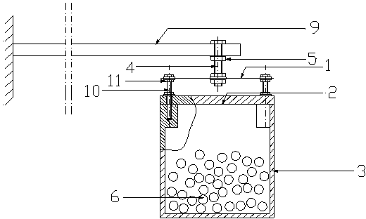
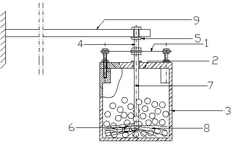
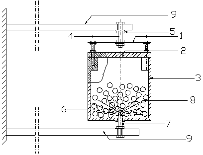
[0021] Please refer to Figure 1 to Figure 3 and combine Figure 4 to Figure 5 As shown, the particle damping shock absorber of the present invention includes a housing 3, damping particles 6 filled in the housing 3 at a certain ratio, the top cover 2 is fastened on the housing 3 with screws, and the top cover 2 and the housing 3 constitute a Particle damping container for particle damping shock absorbers. The first screw 10 and the first nut 11 connect the spring sheet 1 with the particle damping container; the spring sheet 1 has a hole in the middle, and the second screw rod 4 passing through the opening fixes the spring sheet 1 and the main structure 9, And fix it with the second nut 5, so that the particle damping vibration absorber is suspended inside the cavity of the main structure 9 or outside the main structure 9, where the main structure 9 refers to the target system that requires vibration reduction, such as mechanical equipment, aerospace structures, etc.

[0022...


PUM


Abstract

The invention provides a particle damping vibration absorbing device which comprises a spring piece, a particle damping container and a connecting device, wherein damping particles are placed in the particle damping container, and the connecting device is located between the spring piece and the particle damping container. In addition, a perturbator can be additionally arranged on the particle damping vibration absorbing device. The particle damping vibration absorbing device can provide effective vibration control over micro-vibration (vibration acceleration amplitude Aa < 1g) and strong vibration (vibration acceleration amplitude Aa > 1g) of a structure of a mechanical system and overcome the defect that the damping particles can not work in the micro-vibration environment. The particle damping vibration absorbing device with the perturbator additionally arranged is also suitable for controlling vibration in the space weightlessness environment. The particle damping vibration absorbing device is simple in structure, and can be installed inside a main structure or simply hung on the main structure so as to save the space.

Description

Technical field: [0001] The invention relates to a passive vibration control device, in particular to a particle damping vibration absorber, which belongs to the technical field of damping and vibration reduction. Background technique: [0002] As an effective damping technology, non-obstructive particle damping has been extensively studied since it was first proposed by Panossian in the 1990s. Particle damping technology has the advantages of little change to the original structure, can significantly improve the damping of the structure, is suitable for harsh environments, has a wide frequency band of vibration reduction, and the vibration reduction performance will not decrease over time. For the application of particle damping, people often process a certain number of holes on the original structure or directly use the cavity structure of the original structure itself to fill it with damping particles to form a damper; at the same time, independent particles can also be d...

Claims


Application Information

Patent Timeline
Patent Type & Authority Patents(China)
IPC IPC(8): F16F7/01
Inventor 陈前姚冰高雪项红荧
Owner NANJING UNIV OF AERONAUTICS & ASTRONAUTICS
Learn More