
Plug of beverage vessel

A plug body and container technology, which is applied in the field of plug body of beverage containers, can solve problems such as insufficient pressure release, achieve the effect of suppressing splashing and reducing the number of pieces

Active Publication Date: 2013-09-11
THERMOS LLC +1
View PDF6 Cites 12 Cited by
  • Summary
  • Abstract
  • Description
  • Claims
  • Application Information

AI Technical Summary

Problems solved by technology

[0010] For this reason, in order to eliminate the phenomenon that the content splashes from the straw opening, although the straw opening is in a closed state, the air hole is closed / opened / closed when the straw container is opened, and then the straw opening is opened. , however, if the operation of closing / opening / closing the vent hole is too fast, there is still a problem that the pressure cannot be fully released

Method used


Image

  • Plug of beverage vessel
  • Plug of beverage vessel
  • Plug of beverage vessel

Examples


Embodiment 1

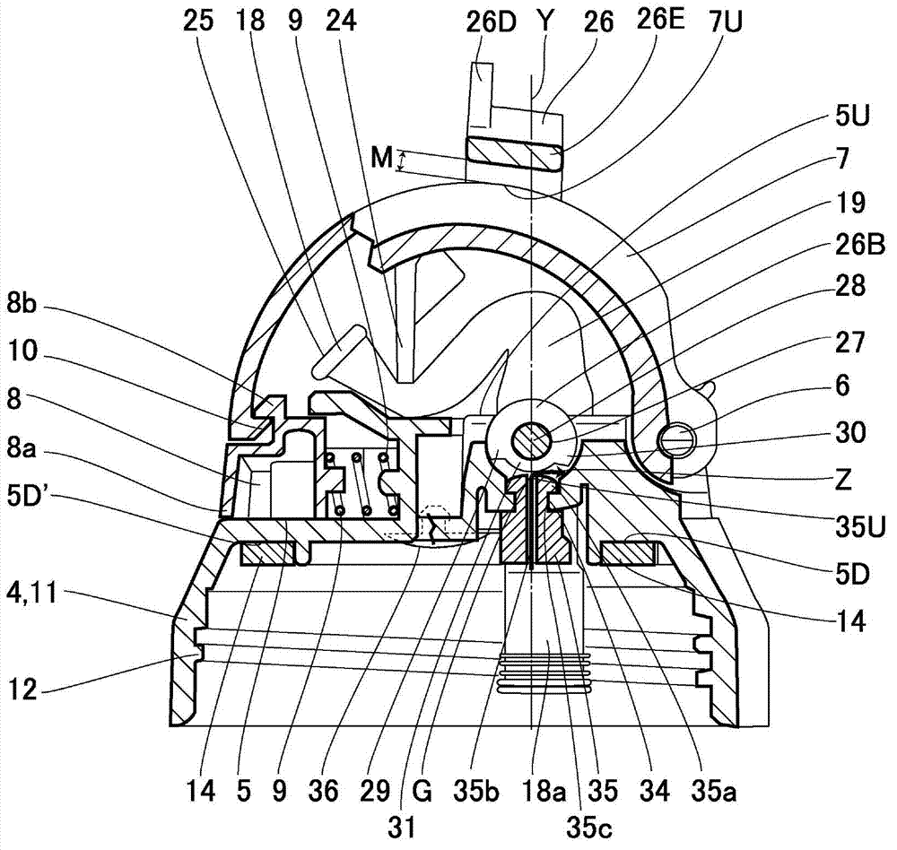
[0045] exist Figure 1-9Among them, symbol 1 is a portable beverage container related to the present invention as a whole, which includes: a metal vacuum-insulated container body 2; and a plug body 4 made of synthetic resin, which is covered on the upper part of the container body Container opening 3. In addition, the base end side of the substantially hemispherical cover 7 is rotatably rotated by the hinge shaft 6 provided as a left and right pair on the upper part of the rear end side of the first top part 5 . In shaft support state. Accordingly, the lid 7 is set in a state that can be moved up and down and freely opened and closed. Here, a lock mechanism 8 is provided on a side opposite to the hinge shaft 6, and the lock mechanism 8 can hold the lid 7 in a closed state by a hook-shaped locking portion 8b provided on the front side. The locking portion 8 b is integrally provided with an operating portion 8 a that exposes the front side and receives an outward bias via a s...

Embodiment 2

[0082] Other embodiments will be described below. The same parts as in the first embodiment are designated by the same symbols, and detailed description thereof will be omitted.

[0083] in such as Figure 10 to Figure 14 In the illustrated embodiment 2, the drinking spout unit 19 is inserted into the drinking spout mounting hole 20 which penetrates through the substantially central portion of the plug body 11 and is cylindrical in plan view. The lower part of the second top 5U. The upper portion of the suction pipe unit 19 is formed in a shape corresponding to the tapered upper mounting hole 44 . In addition, the suction pipe unit 19 further has a fitting concave portion 43 capable of fitting into the fitting convex portion 42 . Furthermore, the crimping lower portion 45 integrally formed with the straw unit 19 is pressed and abutted against the lower portion of the plug body 11 , thereby suppressing the straw unit 19 from being pulled out from the mouthpiece mounting hole...


PUM


Abstract

The invention provides a plug of a beverage vessel. The plug cannot be easily opened due to misoperations or the like, and the operation and closure states of a locking mechanism are definite so that content liquid is prevented from spraying from the front end of a sucker. The plug comprises a plug main body (11), a shaft supporting cover (7), a clamping part (8), a drinking port member (22), and a blocking member (14). The clamping part (8) is arranged in a manner allowing a cover to be kept in or released from the closure state. The drinking port member (22) is clamped in the plug main body (11). The blocking member (14) is pressed against a vessel opening (3) and blocks a vessel main body. The blocking member (14) is clamped in a hole (34), and a ventilation hole (35b) is formed in the through part of the hole (34). The ventilation hole is in the closure state when the cover is in the closure state and temporarily in the open state when a reversing handle member is in a circumferential reversing process, and the ventilation hole is back to the closure state again by virtue of further reversing the reversing handle member, so that the closure state is enabled to be definite and the closure / open / closure action time of the ventilation hole is delayed accurately.

Description

technical field [0001] The invention relates to a plug body of a beverage container. Background technique [0002] It is known that in conventional beverage containers, when a relatively high-temperature liquid is contained in the container main body, the internal pressure in the container main body becomes high, and the beverage retained in the straw will press the air that enters from the outside. When the lid is opened, the content liquid will be sprayed out through the straw part, and then stain clothes and the like. In order to eliminate such danger, by turning the handle and then performing the closing / opening / closing operation, the internal pressure is released and the replacement phenomenon of the content liquid and air in the straw part is eliminated, thereby eliminating the splashing of the content liquid from the front end of the straw (such as Patent Document 1). [0003] In addition, it is also known that the beverage container comprises: a container body, whi...

Claims


Application Information

Patent Timeline
Patent Type & Authority Applications(China)
IPC IPC(8): B65D47/08B65D51/16
Inventor 藤田卫松山真
Owner THERMOS LLC
Learn More