Efficient energy-saving and noise-reducing servo spot-welding equipment

A high-efficiency, energy-saving, spot-welding equipment technology, applied in welding equipment, resistance welding equipment, metal processing equipment, etc., can solve the problems of low welding accuracy, low welding efficiency, and difficult to control accuracy, and reduce one welding point. , the effect of fast running speed and slight noise

Inactive Publication Date: 2015-04-22
宁波长发电器科技有限公司
View PDF6 Cites 0 Cited by
  • Summary
  • Abstract
  • Description
  • Claims
  • Application Information

AI Technical Summary

Problems solved by technology

When welding, put the evaporating tube 91 and the steel wire 92 into the jig and arrange them, and then push the jig to the corresponding position of the welding station. The existing spot welding equipment uses a cylinder to drive the welding head to do reciprocating motion, and the gas consumption is large. , high energy consumption, high noise, every time the cylinder goes back and forth, the welding head completes a welding process, because the stroke of the cylinder is large, its accuracy is difficult to control, and the interval between two round trips of the cylinder is long, so the existing spot welding The welding efficiency of the equipment is low, and the welding accuracy is not high, which cannot meet the needs of efficient industrial production
In addition, when the existing spot welding equipment is welding, it is necessary to put the evaporation tube 91 and the steel wire 92 into the jig and arrange them, and then push the jig to the corresponding position of the welding station by manual operation. The welding process needs to be fed progressively by manual operation. The degree of automation is not high, time-consuming and labor-intensive, and the welding efficiency is low.

Method used


Image

  • Efficient energy-saving and noise-reducing servo spot-welding equipment
  • Efficient energy-saving and noise-reducing servo spot-welding equipment
  • Efficient energy-saving and noise-reducing servo spot-welding equipment

Examples


Embodiment Construction

[0026] The present invention will be further described below in conjunction with embodiment.

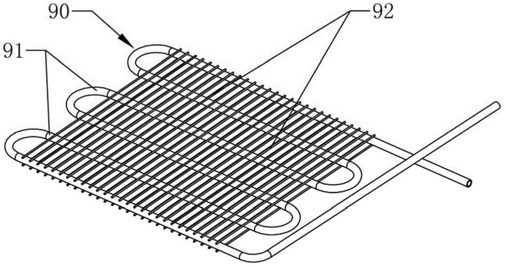
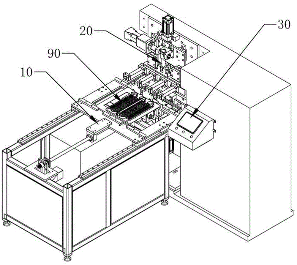
[0027] Such as Figure 1 to Figure 5 As shown, a high-efficiency energy-saving noise reduction servo spot welding equipment includes a welding head lifting mechanism 20, an automatic feeding device 10 and a control module 30, and the welding head lifting mechanism 20 is arranged at the feeding output end of the automatic feeding device 10; The welding head elevating mechanism 20 includes a base 25, a servo reducer 22 and a welding head 23. The servo reducer 22 is arranged on the base 25 and can drive the welding head 23 to perform linear reciprocating motion. The servo reducer 22 passes through the crank The connecting rod mechanism is connected with the welding head 23; the crank connecting rod mechanism includes a crank 221 and a connecting rod 222, the crank 221 is connected with the rotating shaft of the servo reducer 22, and the two ends of the connecting rod 222 are connected w...


PUM


Abstract

The invention relates to the technical field of spot-welding equipment machinery, in particular to efficient energy-saving and noise-reducing servo spot-welding equipment. The servo spot-welding equipment comprises a welding head lifting mechanism, an automatic feeding device and a control module, wherein the welding head lifting mechanism is arranged at a feeding output end of the automatic feeding device, and the control module is in control signal connection with a servo speed reducer and a driving motor respectively. The servo spot-welding equipment adopts the control module for automation control, and the welding head lifting mechanism adopts the servo speed reducer to drive a crank connecting rod to drive a welding head to make lifting motion, so that the traditional air cylinder driving mode is replaced; the automatic feeding device replaces manual operation to achieve automatic feeding; the servo spot-welding equipment is high in automation degree, low in welding energy consumption, higher in welding efficiency and precision, and noise-free; and a requirement on operating conditions of the equipment is low.

Description

technical field [0001] The invention relates to the technical field of spot welding equipment, in particular to a high-efficiency, energy-saving and noise-reducing servo spot welding equipment. Background technique [0002] Evaporators of refrigeration equipment such as figure 1 As shown, it includes a U-shaped curved evaporation tube 91 and several steel wires 92 welded with the evaporation tube 91. Several steel wires 92 are arranged in parallel with the evaporation tube 91. Since each position where the evaporation tube 91 contacts the steel wire 92 needs to be welded, Therefore, there are more welding points. The spot welding equipment for welding the above-mentioned evaporator 90 includes a welding head. For saving welding time and improving welding efficiency, several welding stations are arranged horizontally on the welding head. The points correspond to each other, so that the welding head can complete the welding of a row of welding points in one operation. When ...

Claims


Application Information

Patent Timeline
Patent Type & Authority Patents(China)
IPC IPC(8): B23K11/11B23K11/31B23K11/36
Inventor 李大军
Owner 宁波长发电器科技有限公司
Why Eureka
Try Eureka