Wire harness
A wire harness and line technology, applied in the field of wire harnesses, can solve problems such as the increase in the cost of protectors, and achieve the effects of reducing design man-hours, facilitating design changes, and promoting light weight.
- Summary
- Abstract
- Description
- Claims
- Application Information
AI Technical Summary
Problems solved by technology
Method used
Image


Examples
no. 1 example
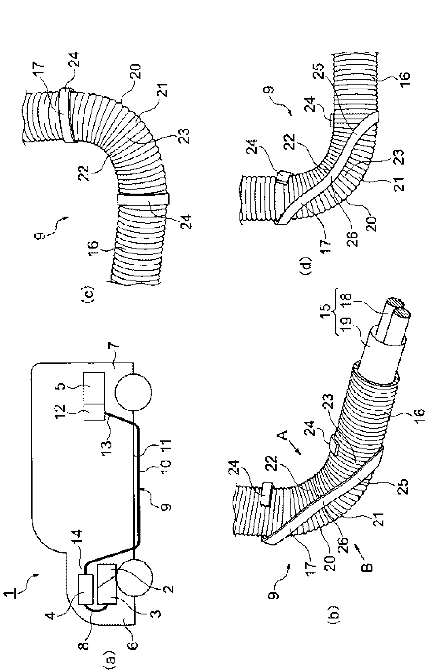
[0063] Hereinafter, a first embodiment will be described with reference to the drawings. figure 1 is a drawing about the wire harness of the present invention, figure 1 (a) is a schematic diagram showing an arrangement example, figure 1 (b) is a perspective view showing the bend and the line holder, figure 1 (c) is a side view of the bend and the line holder when viewed from the direction A, while figure 1 (d) is a side view of the bend and the line holder viewed from the B direction.
[0064] In this embodiment, an explanation will be given regarding an example of the wire harness of the present invention used for a hybrid vehicle (also an electric vehicle).
[0065] exist figure 1In (a) to (d), reference numeral 1 denotes a hybrid vehicle. The hybrid vehicle 1 is a vehicle that mixes the power of an engine 2 and a motor unit 3 and drives the vehicle. Electric power is supplied from a battery 5 (battery pack) to the motor unit 3 via the inverter unit 4 . In the present...
no. 2 example
[0083] Hereinafter, a second embodiment will be described with reference to the drawings. figure 2 (a) and 2(b) are a perspective view and a side view showing another embodiment of the bent portion. In addition, constituent elements similar to those in the first embodiment described above are assigned similar reference numerals, and thus will not be described in detail.
[0084] exist figure 2 In (a) and 2(b), in the wire harness 31 of the second embodiment, the bending object held by the wire holder 17 is different from that of the first embodiment. In other words, the holding object of the line holder 17 is the bent portion 33 of the wire bundle 32 in which a plurality of wires (lead wires) are bundled.
[0085] In the bent portion 33 , reference numeral 34 denotes an outer curvature forming portion on the side where the degree of curvature R is larger. In addition, reference numeral 35 denotes an inner curvature forming portion on the side where the degree of curvature...
no. 3 example
[0088] Hereinafter, a third embodiment will be described with reference to the drawings. figure 2 (c) and 2(d) are perspective and side views showing another embodiment of the line holder. In addition, constituent elements similar to those in the first embodiment described above are assigned similar reference numerals, and thus will not be described in detail.
[0089] exist figure 2 In (c) and 2(d), the wire harness 41 is configured to include the wire assembly 15 , the outer member 16 provided outside the wire assembly 15 , and the wire holder 42 . The line keeper 42 of the third embodiment is different from that of the first embodiment.
[0090] The line holder 42 is a member that holds the bend of the bending portion 20 and holds the course of the wire harness 41 , and is formed by bending a slat having rigidity. Although the final holding shapes are different from each other, this line holder 42 is used in the same way as the line holder 17 of the first embodiment. ...
PUM
 Abstract
Description
Claims
Application Information
 - R&D
- Intellectual Property
- Life Sciences
- Materials
- Tech Scout
- Unparalleled Data Quality
- Higher Quality Content
- 60% Fewer Hallucinations
Browse by: Latest US Patents, China's latest patents, Technical Efficacy Thesaurus, Application Domain, Technology Topic, Popular Technical Reports.
© 2025 PatSnap. All rights reserved.Legal|Privacy policy|Modern Slavery Act Transparency Statement|Sitemap|About US| Contact US: help@patsnap.com