
Deformation monitoring method based on pseudo satellite

A deformation monitoring and pseudolite technology, which is applied in the field of pseudolite-based deformation monitoring, can solve problems such as inability to monitor, and achieve the effect of simplifying pseudolite circuits and ensuring measurement accuracy.

Active Publication Date: 2015-03-11
CHONGQING UNIV
View PDF3 Cites 0 Cited by
  • Summary
  • Abstract
  • Description
  • Claims
  • Application Information

AI Technical Summary

Problems solved by technology

[0004] In view of this, the object of the present invention is to provide a kind of deformation monitoring method based on pseudolite, this method replaces the satellite in GPS with pseudolite to realize building deformation monitoring, not only can inherit the advantage of GPS deformation monitoring method, can overcome simultaneously It has the disadvantage of being unable to monitor in severely shaded areas, and realizes high-precision three-dimensional monitoring

Method used


Image

  • Deformation monitoring method based on pseudo satellite
  • Deformation monitoring method based on pseudo satellite
  • Deformation monitoring method based on pseudo satellite

Examples


Embodiment Construction

[0025] The preferred embodiments of the present invention will be described in detail below with reference to the accompanying drawings.

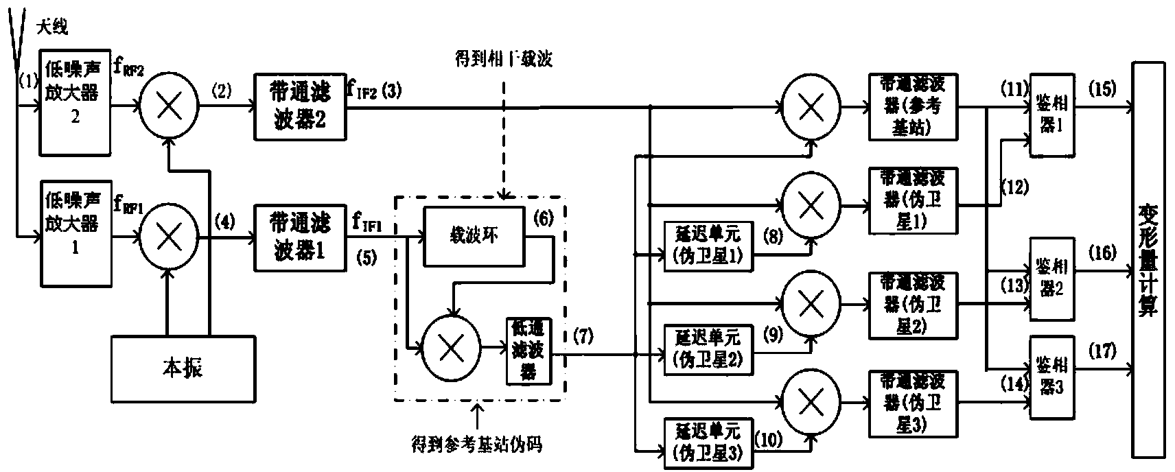
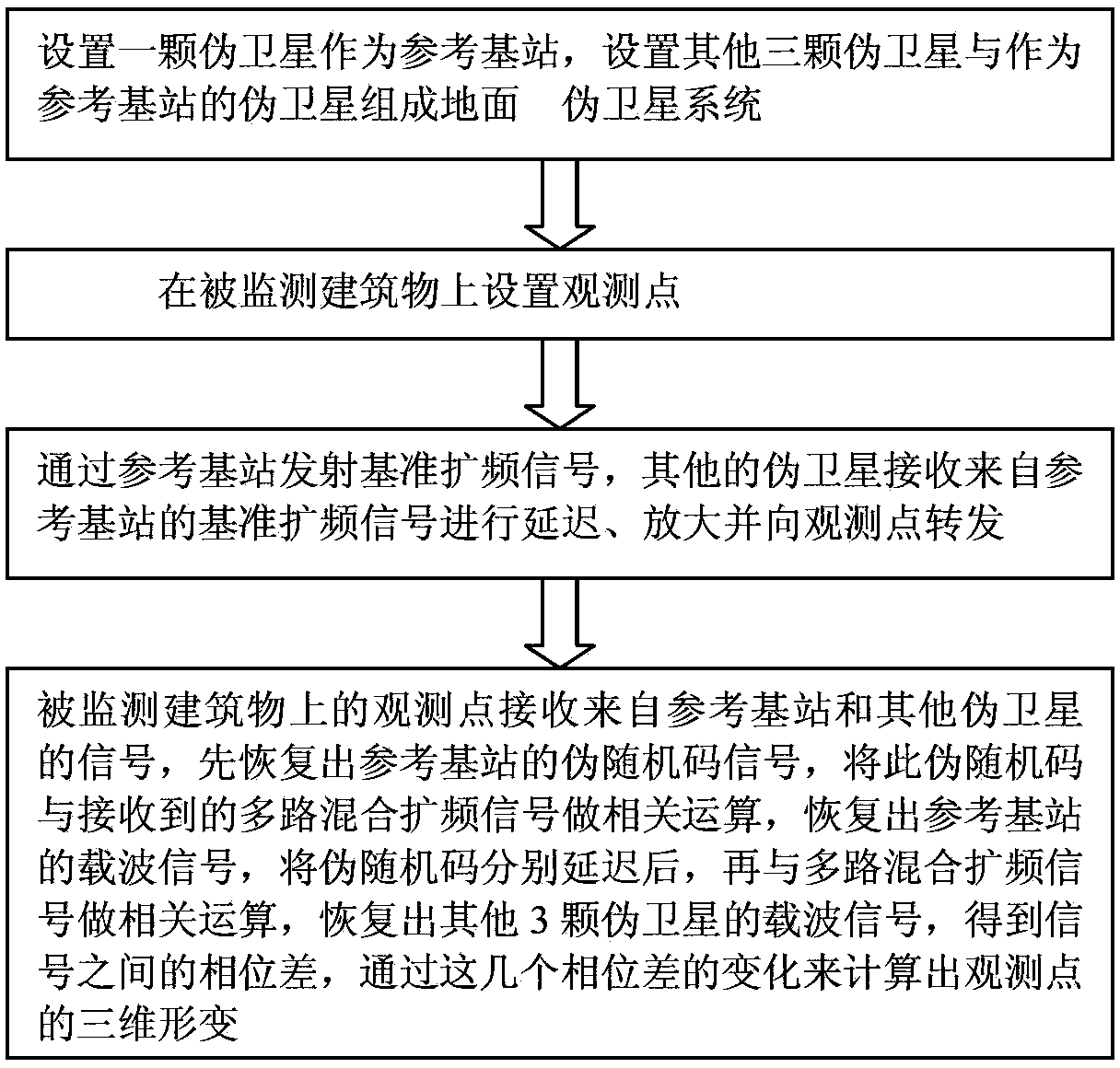
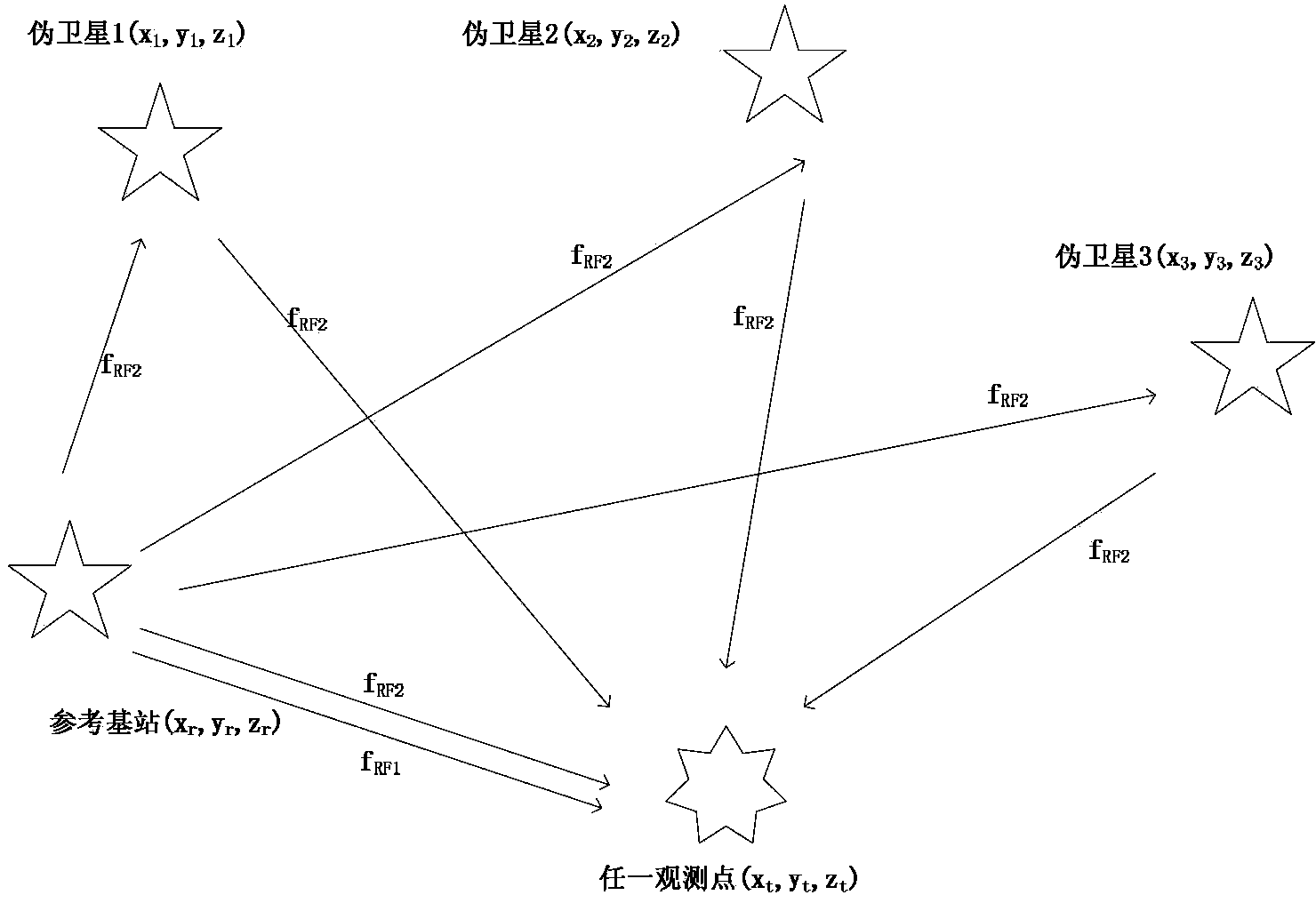
[0026] figure 1 The flow diagram of this method, as shown in the figure, this method includes 4 steps, step 1: set a pseudolite as a reference base station, set other three pseudolites and the pseudolite as a reference base station to form a ground pseudolite system; Step 2: Set the observation point on the monitored building; Step 3: Transmit the reference spread spectrum signal through the reference base station, and other pseudolites receive the reference spread spectrum signal from the reference base station to delay, amplify and forward it to the observation point; Step 4 : The observation point on the monitored building receives signals from the reference base station and other pseudo-satellites, first recovers the pseudo-random code signal of the reference base station, and performs correlation calculations on the pseudo-random code ...


PUM


Abstract

The invention discloses a deformation monitoring method based on a pseudo satellite, and belongs to the technical field of building deformation monitoring. According to the method, a ground pseudo satellite system is arranged to monitor observation points on a building; a reference base station in the pseudo satellite is used for launching benchmark spread spectrum signals, other pseudo satellites receive the benchmark spread spectrum signals coming from the reference base station, delay and amplify the signals and transmit the signals to the observation points; the observation points receive the signals coming from the reference base station and the other pseudo satellites and restore pseudo-random code signals of the reference base station, correlation operation is carried out on the pseudo-random code signals and received multi-path mixing spread spectrum signals, carrier signals of the reference base station are restored, the pseudo-random code signals are delayed respectively, then, the correction operation is carried out on the pseudo-random code signals and the multi-path mixing spread spectrum signals, and carrier signals of the other pseudo satellites are restored; three-dimension deformation of the observation points is calculated through the changing of a phase difference of the signals. According to the method, a system is free of a clock synchronization network, the circuit structure is simple, the pseudo satellites can be arranged optimally, and the measurement precision is high.

Description

technical field [0001] The invention belongs to the technical field of building deformation monitoring, and relates to a deformation monitoring method based on a pseudolite. Background technique [0002] In nature, under the influence of various factors, the shape, size, and position of buildings will change in time domain space, such as the swing of high-rise buildings, the deformation of dams, etc. And when the amount of deformation exceeds the allowable range that the deformable body can bear, it will bring serious disasters to human production and life. Therefore, it is of great significance to monitor the deformation of objects. [0003] In the building deformation monitoring technology, the traditional methods mainly include ground observation monitoring technology, which is mainly based on latitude and longitude, total station, level and other geodetic measurement technologies, but it is not easy to automate and the measurement efficiency is low. With the extensive ...

Claims


Application Information

Patent Timeline
Patent Type & Authority Patents(China)
IPC IPC(8): G01S19/11G01B21/32
Inventor 王韬伍秋黎湧杨力生张洪郑海升李康男高叶霞谢芝茂王坤张潘
Owner CHONGQING UNIV
Learn More