
An anchorage structure displacement monitoring device based on spot displacement change

A technology of displacement monitoring and displacement change, applied in the direction of measuring devices, optical devices, instruments, etc., can solve the problems of monitoring result errors and monitoring accuracy reduction

Active Publication Date: 2019-12-27
重庆市交通工程质量检测有限公司
View PDF10 Cites 0 Cited by
  • Summary
  • Abstract
  • Description
  • Claims
  • Application Information

AI Technical Summary

Problems solved by technology

In the existing patent, the method of using laser to monitor the displacement of the anchorage structure (201210399733.8) has the problem that the laser will be twisted as time goes on, resulting in changes in the shape and position of the spot, which will cause large errors in the monitoring results. The method of monitoring the displacement of the anchor spindle structure (201210394633.6) is not suitable for deeper anchor chambers. When the pressure difference range increases, the monitoring accuracy will decrease accordingly

Method used


Image

  • An anchorage structure displacement monitoring device based on spot displacement change
  • An anchorage structure displacement monitoring device based on spot displacement change

Examples


Embodiment Construction

[0020] The present invention will be further described in detail below in conjunction with the accompanying drawings.

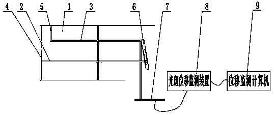
[0021] like figure 1 As shown, the present application discloses an anchorage structure displacement monitoring device based on spot displacement changes, including an anchorage detection rod and an error detection rod arranged in parallel in the anchor chamber. The anchorage detection rod and the error detection rod are uniform in material, length and shape. For the same rigid detection rod, one end of the anchor detection rod is connected to the anchor surface, the anchor detection rod can move along the axis of the anchor detection rod itself with the deformation of the anchor surface, and the other end of the anchor detection rod is slidably installed on the slide of the laser emitting device. In the groove, one end of the error detection rod close to the anchoring surface is connected to the side wall of the anchor chamber through a fixed rod, and the ot...


PUM


Abstract

The invention provides an anchorage structure displacement monitoring device based on optical spot displacement change. In the technical scheme, the anchorage structure displacement monitoring devicecomprises an anchoring detection bar and an error detection bar which are arranged in parallel in an anchorage chamber, wherein one end of the anchoring detection bar is connected to an anchoring surface, the anchoring detection bar can move in the own axis direction along with deformation of the anchoring surface, and the other end of the anchoring detection bar is glidingly mounted in a chute ofa laser emitting device; the end, close to the anchoring surface, of the error detection bar is connected with the side wall of the anchorage chamber through a fixed rod, the other end of the error detection bar is hinged with one end of the laser emitting device, the other end of the laser emitting device faces an optical spot detection target which is connected with an optical spot displacementdevice, and the optical spot displacement monitoring device is connected with a displacement monitoring computer which is used for calculating anchorage structure displacement. Compared with the prior art, deformation of the anchoring surface in the anchorage chamber can be monitored precisely in a long period of time without being affected by depth of the anchorage chamber.

Description

technical field [0001] The invention relates to the technical field of bridge safety monitoring, in particular to an anchor structure displacement monitoring device based on light spot displacement changes. Background technique [0002] Suspension bridge is one of the most commonly used extra-large and large-scale bridge types. These large-scale bridges are located in various traffic arteries, and the investment is huge, and the investment and maintenance costs are the highest among all bridge types. During the operation process, the traffic flow is very large and the load is heavy, which is of great significance to the construction of the national economy that cannot be underestimated. Once a safety accident occurs on these bridges, it will have serious consequences for the country's economic construction and social stability. Since the anchorage of the suspension bridge bears the horizontal force and vertical reaction force from the main cable, it is one of the main beari...

Claims


Application Information

Patent Timeline
Patent Type & Authority Patents(China)
IPC IPC(8): G01B11/02
CPCG01B11/02
Inventor 蓝章礼张洪鲍芳芳周建庭王庆珍
Owner 重庆市交通工程质量检测有限公司
Learn More