
Self-clamping dynamic sealing device capable of feeding electrode wires in wriggled mode

A technology of dynamic sealing and electrode wire, which is applied to the sealing of the engine, accessories, engine components, etc., can solve the problems of increasing the weight of the overall device, unable to discharge debris well, and the size of the device is large, and achieves simple structure and manufacturing. The effect of low cost and improved machining accuracy

Active Publication Date: 2015-04-22
YANTAI UNIV
View PDF6 Cites 0 Cited by
  • Summary
  • Abstract
  • Description
  • Claims
  • Application Information

AI Technical Summary

Problems solved by technology

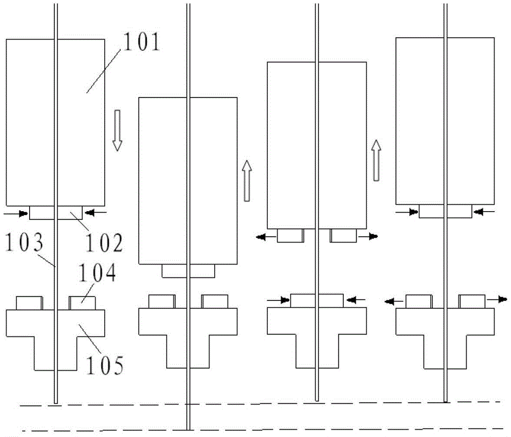
[0009] figure 1 The processing method of medium creep feed can only make the electrode wire creep forward. When processing a tapered hole, the electrode wire will only be processed on one side, and its head will gradually become wedge-shaped, which is not conducive to the improvement of processing accuracy.
[0010] In addition, in order to remove the debris generated during processing and to reduce the temperature of the workpiece and the wire electrode, most of the clamping devices for the creep-feed wire electrode currently use flushing outside the processing position of the workpiece to be punched. Although the external flushing method can reduce the temperature of the workpiece to be punched and the electrode wire, this external flushing method cannot discharge the debris that enters the wire electrode during processing; at the same time, the external flushing method will cause flushing waste
[0011] Therefore, it is thought to use the internal flushing of the electrode wire, the electrode wire is creep-feed, and the electrode wire is rotated at the same time. Since the electrode wire clamping of the existing creep-feed electrode wire clamping device mainly adopts a mechanical clamping method, There will be a certain gap between the electrode wire and the clamping device in this clamping method, so it is necessary to seal the clamping device of the peristaltic feeding electrode wire. If an additional sealing device is added, the weight of the overall device will be increased. As a result, the overall size of the device is too large; if the traditional sealing method is used, it will not be able to perform a good sealing effect; if a special sealing method is used, the structure of the device will be complicated

Method used


Image

  • Self-clamping dynamic sealing device capable of feeding electrode wires in wriggled mode
  • Self-clamping dynamic sealing device capable of feeding electrode wires in wriggled mode

Examples


Embodiment Construction

[0030] The principles and features of the present invention are described below in conjunction with the accompanying drawings, and the examples given are only used to explain the present invention, and are not intended to limit the scope of the present invention.

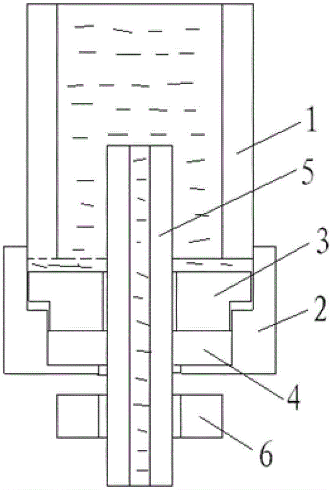
[0031] Such as figure 2 As shown, a self-clamping dynamic sealing device for peristaltic feeding electrode wire, including a hollow motor shaft 1, a gland 2, a hard sealing ring 3 and a soft sealing ring 4;

[0032] The bottom end of the hollow motor shaft 1 and the upper end of the gland 2 are connected by thread sealing, and an inner cavity is formed inside the gland 2, and the hard seal ring 3 and the soft seal ring 4 are filled in the gland 2 from top to bottom. In the inner cavity; the hollow electrode wire 5 passes through the hollow main shaft 1 of the motor, the hard sealing ring 3, the soft sealing ring 4 and the gland 2; there is a gap between the upper end surface of the hard sealing ring 3 and the lower...


PUM

PropertyMeasurementUnit
widthaaaaaaaaaa

Abstract

The invention relates to a self-clamping dynamic sealing device capable of feeding electrode wires in a wriggled mode. The self-clamping dynamic sealing device capable of feeding the electrode wires in the wriggled mode comprises a hollow main shaft of a motor, a gland, a rigid sealing ring and a flexible sealing ring. The bottom end of the hollow main shaft of the motor is linked with the gland in a threaded and sealed mode. An inner cavity is formed in the gland. The rigid sealing ring and the flexible sealing ring are filled in the inner cavity of the gland from top to bottom. Hollow electrode wires penetrate through the hollow main shaft of the motor, the rigid sealing ring, the flexible sealing ring and the gland. A seam is reserved between the upper end face of the rigid sealing ring and the lower end face of the hollow main shaft of the motor. The inner side surface of the rigid sealing ring is in clearance fit with the hollow electrode wires and a seam is reserved between the outer side surface of the rigid sealing ring and the inner side face of the gland. The upper end face of the flexible sealing ring is contacted with the rigid sealing ring. The inner side face of the flexible sealing ring is clearance fit with the hollow electrode wires. The outer side face of the flexible sealing ring is contacted with the inner side face of the gland. The lower end face of the flexible sealing ring is contacted with the bottom face in the gland. The self-clamping dynamic sealing device capable of feeding the electrode wires in the wriggled mode is simple in structure, low in cost and capable of automatically clamping and dynamically sealing the electrode wires.

Description

technical field [0001] The invention relates to a clamping device for electrode wires, in particular to a self-clamping dynamic sealing device for creep-feeding electrode wires. Background technique [0002] With the gradual development of science and technology, products are gradually becoming miniaturized and refined, which puts forward higher requirements for product processing equipment, especially in the field of micro-processing, which requires better equipment stability and higher precision. In terms of micromachining, especially in EDM, higher requirements are put forward, especially the feeding method of electrode wire in EDM. The creep-feed concept was born, and it works to great effect. [0003] The traditional clamping device for peristaltic feeding wire electrode such as figure 1 As shown, it includes a servo drive module 101, a first clamp 102, an electrode wire 103, a second clamp 104, and a guide head 105. The bottom surface of the servo drive module 101 is...

Claims


Application Information

Patent Timeline
Patent Type & Authority Patents(China)
IPC IPC(8): B23H11/00B23H9/14F16J15/16
Inventor 柴永生张龙范文龙刘兆全于志强
Owner YANTAI UNIV
Learn More