Metal pouring die of hydraulic core pulling structure

A core-pulling structure and metal pouring technology, which is applied to metal processing equipment, cores, manufacturing tools, etc., can solve the problems of high guide and fit precision requirements, non-adjustable stroke distance, and narrow application range of molds, etc., to achieve novel structural design , reduced labor costs, and strong structural reliability

Active Publication Date: 2015-06-24
NINGBO HUASHUO MOLDING & MACHINE
View PDF8 Cites 0 Cited by
  • Summary
  • Abstract
  • Description
  • Claims
  • Application Information

AI Technical Summary

Problems solved by technology

[0003] The structure of mechanical core-pulling has the following defects due to its design principles: 1. The mechanical method is easy to design, and the overall structure is complex and bulky; It is more difficult to manufacture; 3. Mechanical mode, when the mold is used frequently, the wearability of each supporting part is relatively large, and the overall use is shortened; 4. Mechanical core-pulling mode, its stroke and core-pulling distance are all fixed-length structures, and the stroke distance It cannot be adjusted. In case of a slight change in the core pulling requirements, the mold needs to be redesigned, so the scope of application of the mold is narrow
[0004] To sum up, the existing mechanical core-pulling mode casting molds still have major deficiencies, and the overall technology is not yet perfect.

Method used


Image

  • Metal pouring die of hydraulic core pulling structure
  • Metal pouring die of hydraulic core pulling structure
  • Metal pouring die of hydraulic core pulling structure

Examples


Embodiment Construction

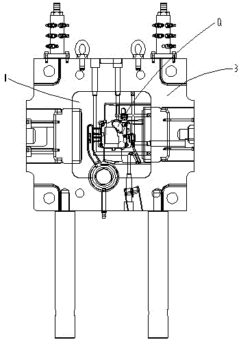
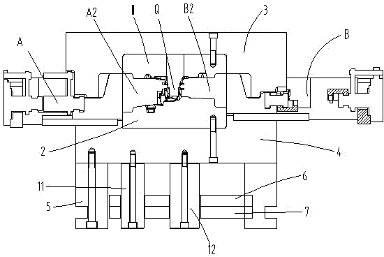
[0036] The present invention will be described in further detail below in conjunction with the embodiments of the drawings.

[0037] Such as Figure 1 to Figure 16 As shown, the icon numbers are explained as follows: upper mold core 1, lower mold core 2, upper mold frame 3, lower mold frame 4, mold foot 5, upper top plate 6, lower top plate 7, guide sliding rod 8, first support pillar 11 , The second brace 12, side core pulling assembly A, side core pulling hydraulic cylinder A1, side core pulling block A2, side core pulling seat A3, side stroke switch A4, side stroke switch lever A5, side Two core pulling assembly B, side two core pulling hydraulic cylinder B1, side two core pulling block B2, side two core pulling seat B3, side two stroke switch B4, side two stroke switch lever B5, side three core pulling assembly C, side three Core pulling hydraulic cylinder C1, side three core pulling block C2, side three oblique guide block C3, inner concave chute body C31, side three slidin...


PUM


Abstract

The invention discloses a metal pouring die of a hydraulic core pulling structure. The metal pouring die comprises an upper die frame, a lower die frame, an upper die core and a lower die core, wherein the upper die frame and the lower die frame are vertically fastened, the upper die core is embedded on the bottom face of the upper die frame, the lower die core is embedded on the top face of the lower die frame, the upper die core and the lower die core form a forming cavity of the metal pouring die when being vertically matched, a first-side core pulling component and a second-side core pulling component are allocated on the left side and the right side of the lower die frame respectively, and a third-side core pulling component and a fourth-side core pulling component are allocated on the front side and the rear side of the lower die frame respectively. According to forming complexity of the metal pouring die, the core pulling components are independently allocated on four sides of the die, so that the metal pouring die is reasonable in design, flexible to operate and suitable for convenient manufacturing of different models. The core pulling components are driven by hydraulic oil, so that the metal pouring die is high in automation degree, direct in control, high in working efficiency and low in labor cost. The metal pouring die is controlled by travel switches, and core pulling strokes are designed to be adjustable, so that the metal pouring die is convenient and fast to operate and wide in application range.

Description

Technical field [0001] The invention relates to the technical field of molds, in particular to a metal casting mold with a hydraulic core pulling structure. Background technique [0002] Existing casting molds have a relatively complicated shape of the casting cavity, so this type of mold generally has a core-pulling structure, but most of the core-pulling operation adopts a mechanical method, that is, the core body in the cavity is realized by the mechanical operation when the mold is opened and closed. Extract and run. [0003] The mechanical core-pulling structure has the following defects due to its design principle basis: 1. The mechanical method is easy to be designed, and the overall structure is complex and bulky; 2. The mechanical drive mode requires high coordination accuracy of each guide, which is easy to cause actual It is more difficult to make; 3. Mechanical mode, when the mold is used frequently, each accessory is more wear-resistant, and the overall use is shorten...

Claims


Application Information

Patent Timeline
Patent Type & Authority Patents(China)
IPC IPC(8): B22D29/00B22C9/00
Inventor 旷鑫文
Owner NINGBO HUASHUO MOLDING & MACHINE
Why Eureka
Try Eureka