Separator for separating solid particles from a vapour-gas mixture

A gas mixture and solid particle technology, applied in the field of separators, can solve the problems of reducing the separation efficiency of the device, and achieve the effect of avoiding penetration and sticking

Active Publication Date: 2013-08-28
ENEFIT OUTOTEC TECH OU
View PDF9 Cites 0 Cited by
  • Summary
  • Abstract
  • Description
  • Claims
  • Application Information

AI Technical Summary

Problems solved by technology

Builds up a dust loop that reduces the separation efficiency of the entire unit

Method used


Image

  • Separator for separating solid particles from a vapour-gas mixture
  • Separator for separating solid particles from a vapour-gas mixture
  • Separator for separating solid particles from a vapour-gas mixture

Examples


Embodiment Construction

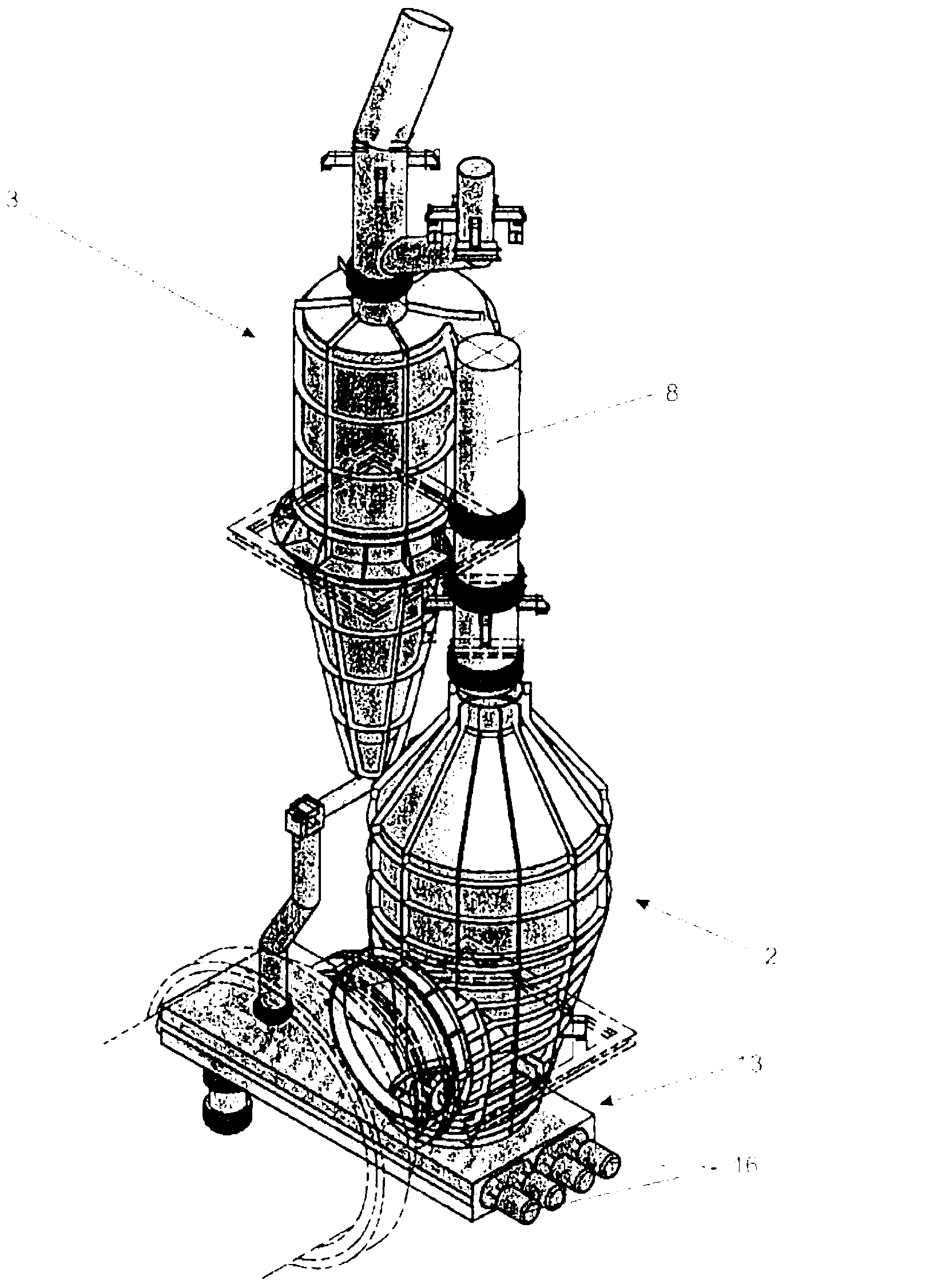
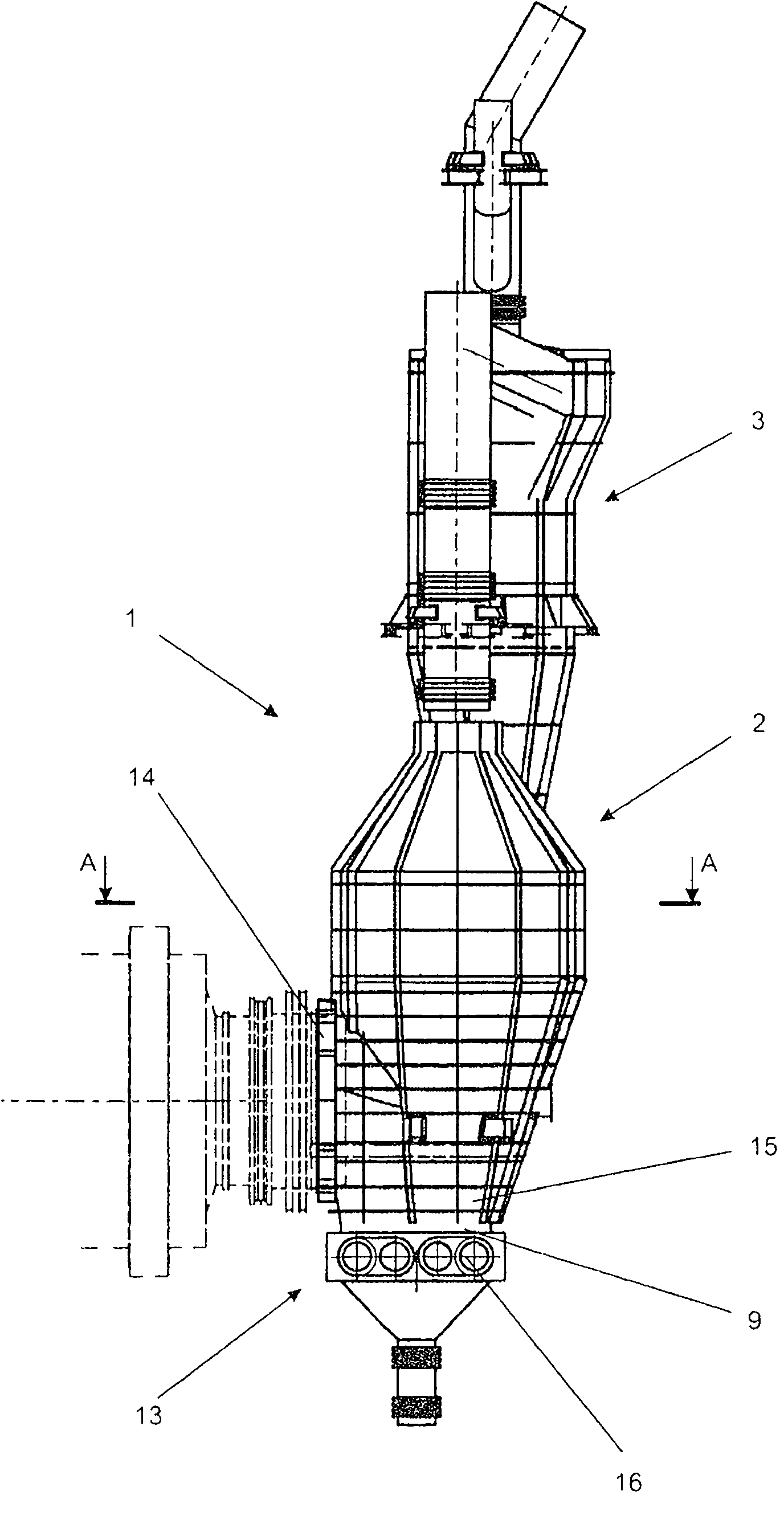
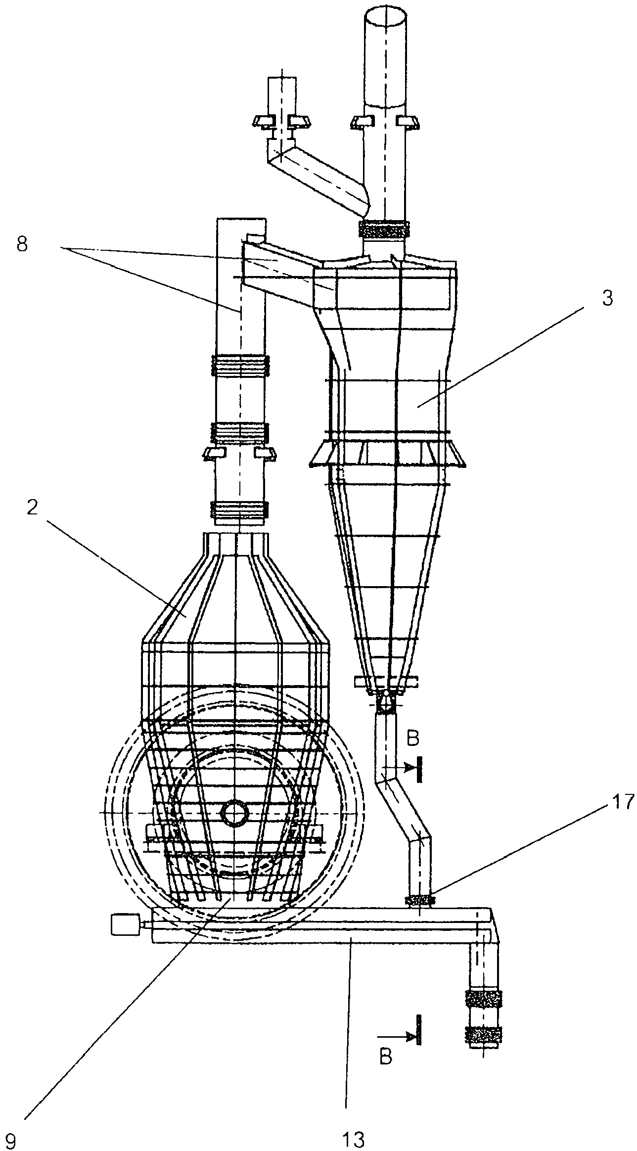
[0036] Pyrolysis of pulverized fossil fuels (e.g. oil shale) or materials containing organic matter occurs in a retort using a solid heat carrier process and thereafter, up to 1200 g / Nm 3 The steam-gas mixture (at standard pressure and temperature) containing semi-coked particles, hydrocarbon vapors, water vapour, cracked gas and other gases is directed to a separator 1 comprising a dedusting chamber 2 for separating from the steam The gas mixture separates solid particles. The temperature of the steam gas mixture entering the processing unit is about 460°C to 520°C.

[0037] The solids contained in the steam-gas mixture are separated in this device by the gravitational settling of the particles in the dedusting chamber 2 and by the centrifugal force in the cyclone 3 .

[0038] figure 1 A separator 1 according to the invention for separating solid particles from a vapor-gas mixture, shown in , comprises a dedusting chamber 2 having a main body 4 (see Figure 4 ), the outer ...


PUM


Abstract

The present invention is related to the separator for separating solid particles from a vapour-gas mixture, and particularly to the structure of a dust chamber (2) as installed in the plant for processing fossil fuels or materials containing organic matter. The dust chamber (2) comprises a main body (4) having an inlet (14) for a vapour-gas mixture containing semi-coke particles and an outlet chute (9) for removal of semi-coke particles, wherein the upper part of the main body (4) is connected to the inlet of a cyclone (3) for removal of fine semi-coke particles from the vapour-gas mixture and wherein a screw conveyor unit (13) is connected to the bottom part of the main body (4). Said main body (4) is covered with an external insulation (5). Electrical trace heating cables (7) are in contact with the external surface of the main body (4) of the dust chamber (2).

Description

technical field [0001] The invention relates to a separator for separating solid particles from a vapor-gas mixture. The separator consists of: a dust chamber, a cyclone, a dust discharge conveyor and interconnecting pipes and chutes between said components. Separators are part of equipment for treating solids containing fossil or organic hydrocarbon substances by thermal treatment. Background technique [0002] Document EE 200100111 discloses a separator for separating solid particles from a vapor-gas mixture, wherein the separator comprises: a dedusting chamber (main body) with a refractory lining placed on its inner surface; An inlet for the steam-gas mixture to the main body of the dedusting chamber; first and second stage cyclone separators, which are placed inside the main body of the dedusting chamber; and an outlet for separated semi-coked particles. [0003] For technical reasons, the vapor gas mixture should not condense during contact with the walls of the conta...

Claims


Application Information

Patent Timeline
IPC IPC(8): B01J8/00
CPCB01J8/0055B01D45/16B08B1/00
Inventor M·施特勒德C·文特兰德B·罗斯A·凯达洛夫K·凯达洛夫
Owner ENEFIT OUTOTEC TECH OU
Why Eureka
Try Eureka