Ultrasonic endoscope

An ultrasonic and endoscope technology, applied in the field of ultrasonic endoscope, can solve the problems of signal line damage, signal line easily damaged, signal line disconnection, etc.

Active Publication Date: 2013-08-28
OLYMPUS CORP
View PDF6 Cites 12 Cited by
  • Summary
  • Abstract
  • Description
  • Claims
  • Application Information

AI Technical Summary

Problems solved by technology

Therefore, when the assembly operator inserts the vibrator unit into the housing portion of the case, the bending stress concentrates on the connecting portion between the vibrator unit and the cable unit, and the signal lines in the cable unit are easily damaged. If the damage is large, the The internal signal line may be disconnected
[0008] In the past, such a problem that the bending stress concentrates on the connecting portion between the vibrator unit and the cable unit during assembly and causes damage to the signal lines in the cable unit has not been considered.
[0009] In the proposal of the ultrasonic endoscope having the above-mentioned high thermal conductivity layer, the high thermal conductivity layer extending toward the base end side is disclosed, but in this proposal, no consideration is given to the vibrator unit and the cable that are concentrated during assembly as described above. Countermeasures for Bending Stress at Connections Between Units

Method used


Image

  • Ultrasonic endoscope
  • Ultrasonic endoscope
  • Ultrasonic endoscope

Examples


no. 1 Embodiment approach )

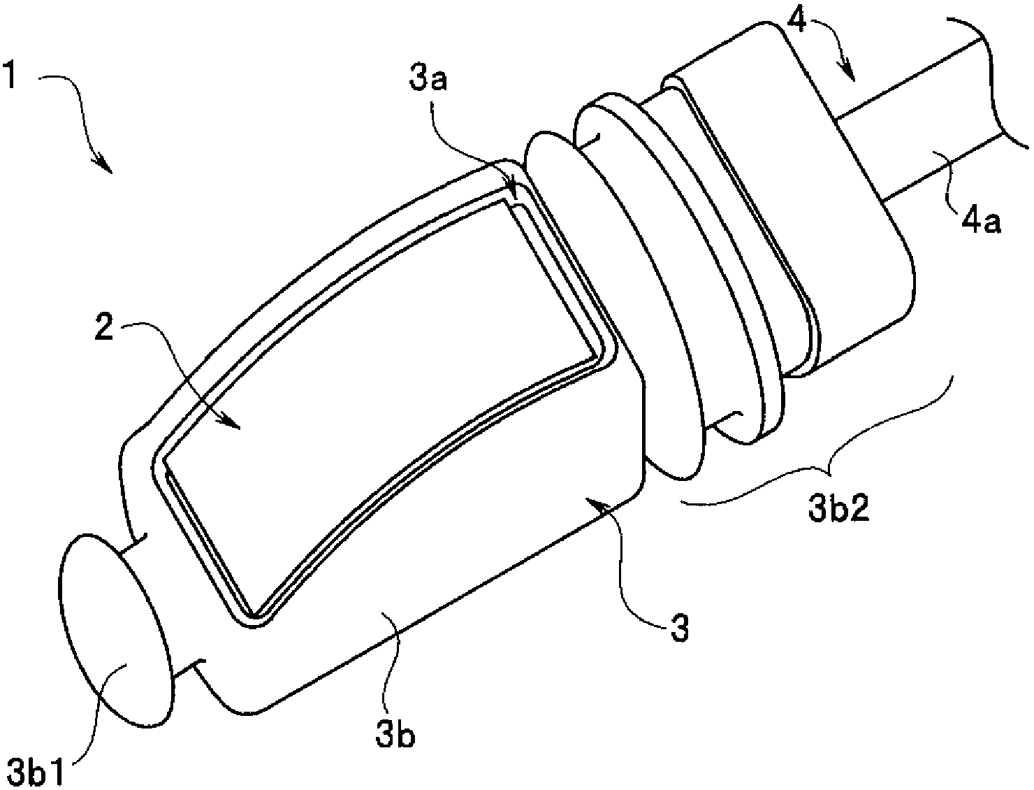
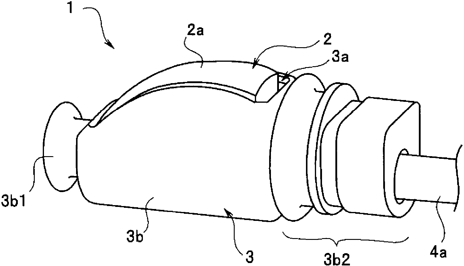
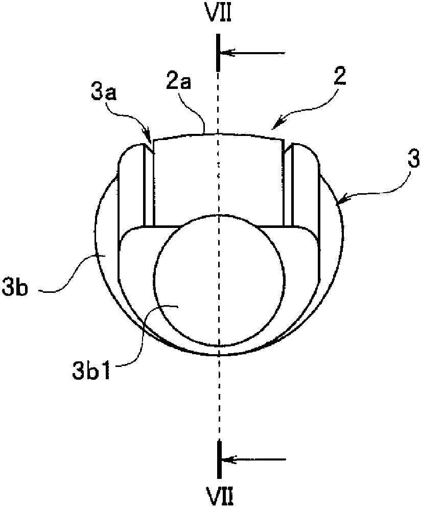
[0043] figure 1 and figure 2 It is an external view of the distal end unit of the ultrasonic endoscope according to the first embodiment of the present invention. figure 1 It is a perspective view of the front end unit viewed obliquely from above the front side, figure 2 It is a perspective view of the front end unit viewed from the rear slightly obliquely in the horizontal direction. image 3 It is a diagram when the distal end unit 1 is viewed from axially forward.

[0044] The top unit 1 mainly includes a vibrator unit 2, a casing 3, a cable unit 4 and a shielding box 5 (in figure 1 , figure 2 , image 3 not shown in the figure). The distal end unit 1 is configured such that the vibrator unit 2 is housed in the housing portion 3 a 2 of the case 3 , and the cable 4 a of the cable unit 4 extends from the base end side of the case 3 . The distal end unit 1 is provided in a distal hard member of an insertion portion of an ultrasonic endoscope to constitute a distal en...

Deformed example 1

[0076] Figure 9 and Figure 10 It is a figure for demonstrating the extension part of this modification 1. Figure 9 It is a perspective view of the shield case 5 having the extension part of Modification 1. FIG. Figure 10 It is a figure which looked at the shielding case 5 from the proximal direction. exist Figure 9 and Figure 10 In , the same reference numerals are assigned to the same constituent elements as those in the above-mentioned embodiment, and description thereof will be omitted.

[0077] Such as Figure 9 As shown, the extension portion 18A of this modified example is disposed on the upper surface side of the outlet 17 and has a curved shape protruding to the upper surface side. More specifically, as Figure 10 As shown, the extension portion 18A has a groove shape obtained along a part of the shape of the outlet 17 .

[0078] Since the extension portion 18A of this modified example has an upwardly protruding curved surface shape, when a bending stress...

Deformed example 2)

[0081] Figure 11 , Figure 12 and Figure 13 It is a figure for demonstrating the extension part of this modification 2. Figure 11 It is a perspective view of the shield box 5 having the extension part of the second modification. Figure 12 It is a figure which looked at the shield case 5 which has the extension part of this modification 2 from a base end direction. Figure 13 It is a sectional view showing a state in which the vibrator unit 2 is accommodated in the accommodation portion 3 a of the case 3 . exist Figure 11 ~ Figure 13 In , the same reference numerals are assigned to the same constituent elements as those in the above-mentioned embodiment, and description thereof will be omitted.

[0082] Such as Figure 11As shown, although the extension part 18B of this modification is plate-shaped, it has the convex part 18Ba which protrudes to the upper surface side in a part. A part of the inner peripheral surface of the cable insertion passage 21 is provided wit...


PUM


Abstract

An ultrasonic endoscope is provided with: a vibrator unit (2) which has an upper surface, a bottom surface, and side surfaces connecting the upper surface and the bottom surface and which performs the transmission and reception of an ultrasonic wave on the upper surface side; a cable (4a) which transmits and receives an electric signal from the vibrator unit (2) and which is connected to a side surface; an electrically conductive sealed case (5) which covers the side surfaces and the bottom surface, the electrically conductive sealed case (5) having an outlet opening (17), out of which the cable (4a) is led, and also having a flexible extended section (18) which is extended from at least the upper surface side of the outlet opening (17); and a housing (3) which holds the vibrator unit (2) through the sealed case (5) and which has a cable insertion path (21) into which the cable (4a) and the extended section (18) are inserted.

Description

technical field [0001] The invention relates to an ultrasonic endoscope. Background technique [0002] Conventionally, ultrasonic endoscope devices have been widely used in the medical field. In an ultrasonic endoscope, an ultrasonic probe for transmitting and receiving ultrasonic waves is provided at a distal end portion of an elongated endoscope insertion portion. The ultrasonic endoscope apparatus transmits ultrasonic waves from the ultrasonic probe, and generates and displays an ultrasonic image of the subject based on ultrasonic echo signals received from the subject. [0003] A vibrator unit having a vibrating portion is disposed inside an ultrasonic probe provided at a distal end portion of an insertion portion of an ultrasonic endoscope. The vibrator unit is accommodated in the case. Furthermore, since the insertion portion is inserted into the subject, the vibrator unit is provided in a grounded shield case in consideration of electrical safety against the subjec...

Claims


Application Information

Patent Timeline
Patent Type & Authority Applications(China)
IPC IPC(8): A61B8/12A61B1/00
CPCA61B8/12A61B1/0008A61B1/00177A61B8/4483A61B1/00096A61B1/00114A61B1/00117A61B1/00119A61B1/05A61B1/12A61B8/445A61B8/4494A61B1/005A61B1/00094A61B1/0011A61B1/07
Inventor 大岸梢入江圭
Owner OLYMPUS CORP
Why Eureka
Try Eureka