Quasi-single-stage high power factor circuit and device with primary side constant current control

A high power factor, constant current control technology, applied in the direction of output power conversion device, high-efficiency power electronic conversion, conversion equipment with intermediate conversion to AC, etc., can solve the problems of stroboscopic and inapplicable, and achieve simple circuit structure , reduce ripple current, and reduce circuit cost

Active Publication Date: 2015-08-26
HANGZHOU SILAN MICROELECTRONICS
View PDF5 Cites 2 Cited by
  • Summary
  • Abstract
  • Description
  • Claims
  • Application Information

AI Technical Summary

Problems solved by technology

[0006] figure 2 The advantage of the single-stage conversion circuit shown is that the circuit structure is simple and the circuit cost is low. The disadvantage is that there is a large ripple current (usually 100Hz ripple current) in the output LED load, which will cause flicker and cannot be applied to some pairs. Applications with high stroboscopic requirements

Method used


Image

  • Quasi-single-stage high power factor circuit and device with primary side constant current control
  • Quasi-single-stage high power factor circuit and device with primary side constant current control
  • Quasi-single-stage high power factor circuit and device with primary side constant current control

Examples


no. 1 example

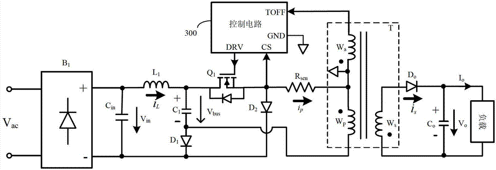
[0046] refer to image 3 , image 3 Shows the quasi-single-stage high power factor device of the first embodiment, including a quasi-single-stage high power factor circuit and a control circuit 300, wherein the quasi-single-stage high power factor circuit includes a rectifier bridge B1, an input capacitor C in , inductance L 1 , Bus capacitance C 1 , the first diode D 1 , switch tube Q 1 , the second diode D 2 , Sampling resistor R sen , Transformer T (including the primary winding W p , secondary winding W s and the auxiliary winding W a ), output diode D o and the output capacitor C o .

[0047] Further, the rectifier bridge B 1 The input terminal of the AC power supply signal is connected and rectified, and the rectifier bridge B 1 The positive output terminal is connected to the input capacitor C in The first end of the inductor L 1 The first end of the bridge rectifier B 1 The negative output terminal is connected to the input capacitor C in The second en...

no. 2 example

[0057] refer to Figure 7 , shows the quasi-single-stage high power factor device with constant current control on the primary side of the second embodiment. The principle of the second embodiment is the same as that of the first embodiment, except that it adopts a non-isolated structure. This embodiment includes a quasi-single-stage high power factor circuit and control circuit 300 . Among them, the quasi-single-stage high power factor circuit includes rectifier bridge B1, input capacitor C in , inductance L 1 , Bus capacitance C 1 , the first diode D 1 , switch tube Q 1 , the second diode D 2 , Sampling resistor R sen , Transformer T (including the primary winding L 2 and the auxiliary winding W aux ), the output diode Do and the output capacitor C o .

[0058] Further, the rectifier bridge B 1 The input terminal receives the AC power signal, and the rectifier bridge B 1 The positive output terminal of the input capacitor C in The first end of the inductor L 1T...

no. 3 example

[0064] refer to Figure 10 , shows the quasi-single-stage high power factor device of the primary side constant current control of the third embodiment. The main circuit of this embodiment is basically the same as that of the aforementioned first embodiment, and the working principle is also basically the same, so it will not be described in detail. The main circuit of this embodiment and image 3 The difference of the first embodiment shown is that the contact between the control circuit 400 and the main circuit changes. In this embodiment, the sampling resistor R sen The first terminal of the sampling resistor Rsen is grounded, and the second terminal of the sampling resistor Rsen is connected to the current sampling terminal CS of the control circuit 400. Therefore, the current information sent to the control circuit 400 is the negative current information of the primary winding Wp of the transformer. After the reverse, the same can be achieved with image 3 The basic fu...


PUM


Abstract

The invention provides a primary side constant current controlled quasi single-stage high power factor circuit and device. The circuit comprises a rectifier bridge, an input capacitor, an inductor, a bus capacitor, a first diode, a switching tube, a second diode, a sampling resistor and a transformer, wherein the first end of the inductor is connected with the first end of the input capacitor, and the first end of the bus capacitor is connected with the second end of the inductor; the anode of the first diode is connected with the second end of the bus capacitor, and the cathode of the first diode is connected with the negative output end of the rectifier bridge; the first power end of the switching tube is connected with the second end of the inductor, and the control end of the switching tube receives the external driving signals; the anode of the second diode is connected with the second power end of the switching tube, and the cathode of the second diode is connected with the negative output end of the rectifier bridge; the first end of the sampling resistor is connected with the second power end of the switching tube, and the dotted terminal of the primary side winding of the transformer is connected with the second end of the sampling resistor; and the non-dotted terminal of the primary side winding of the transformer is connected with the second end of the bus capacitor, and the transformer is coupled with a load. The circuit provided by the invention has the advantage of lower cost compared with the traditional two-stage circuit, and has the advantage of reduction in ripple current of the load compared with the traditional single-stage circuit.

Description

technical field [0001] The invention relates to switching power supply technology, in particular to a quasi-single-stage high power factor circuit and device with constant current control on the primary side. Background technique [0002] Due to the presence of non-linear components and energy storage components in most electrical equipment at present, the input AC current waveform will be severely distorted, and the input power factor of the grid side is very low. In order to meet the harmonic requirements of the international standard IEC61000-3-2, Power factor correction (PFC) devices must be added to these electrical appliances. In addition, some electrical equipment such as LED drivers require the output constant current function. [0003] In order to meet the above two requirements, a circuit structure of the prior art is as follows figure 1 The two-stage structure shown. Wherein, the AC input power supply is connected to the two input terminals of the rectifier bri...

Claims


Application Information

Patent Timeline
Patent Type & Authority Patents(China)
IPC IPC(8): H02M3/28H02M1/42H02M1/14
CPCY02B70/126Y02B70/10
Inventor 谢小高叶美盼蔡拥军吴建兴
Owner HANGZHOU SILAN MICROELECTRONICS
Why Eureka
Try Eureka