Isolated type power circuit and circuit and method for transmitting control signals thereof
A technology for controlling signals and power circuits, applied in the field of electronics, can solve the problems of inability to realize accurate and fast control of power circuits, increase in size and cost of power circuits, and poor effectiveness of control signals, so as to improve safety and reliability and reduce costs. , the effect of small size
- Summary
- Abstract
- Description
- Claims
- Application Information
AI Technical Summary
Problems solved by technology
Method used
Image
Examples
Embodiment 1
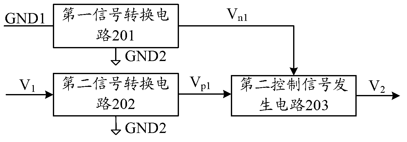
[0068] figure 2 It is a schematic structural diagram of a control signal transmission circuit used in an isolated power supply circuit provided in this embodiment.
[0069] see figure 2 As shown, the control signal transmission circuit of this embodiment mainly includes: a first signal conversion circuit 201, a second signal conversion circuit 202, and a second control signal generation circuit 203. The main connections and working principles are as follows:
[0070] The first signal conversion circuit 201 is connected between the first ground level GND1 and the second ground level GND2 in the isolated power supply circuit, wherein the first ground level GND1 contains the ground line noise signal VGND1; the first signal conversion circuit 201 is used to obtain the first ground noise component VGND1 according to the ground noise signal VGND1 n1 , the first ground noise component V n1 First proportional to the ground noise signal VGND1.
[0071] In this embodiment, the imp...
Embodiment 2
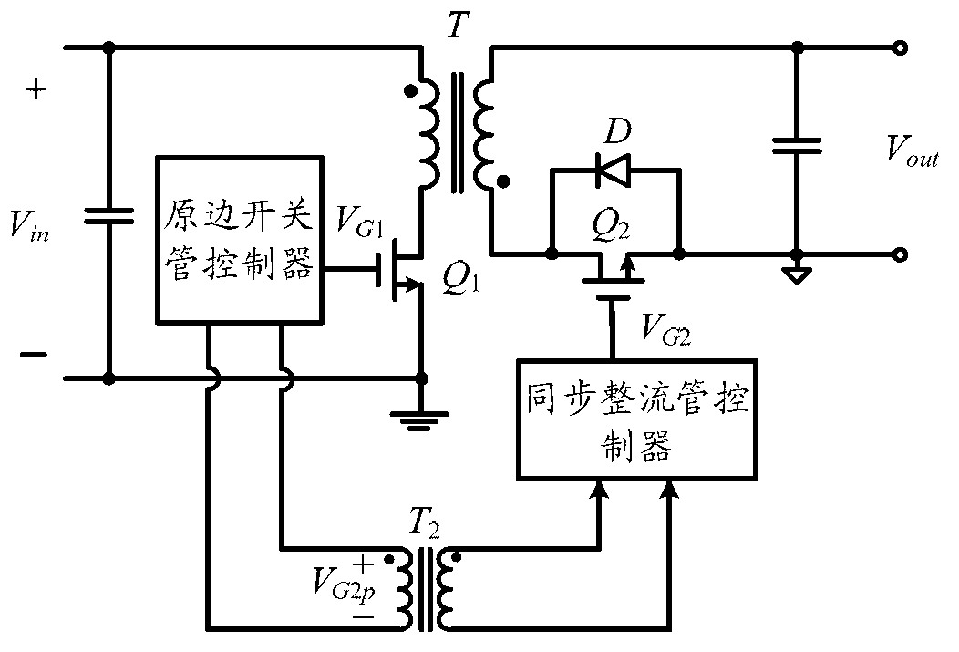
[0082] Figure 4 This embodiment provides a schematic diagram of a circuit using the control signal transmission circuit of this embodiment to control the flyback synchronous rectification switching power supply circuit.
[0083] see Figure 4 As shown, in the flyback synchronous rectification switching power supply, the primary switching tube controller outputs the first control signal V1 to control the primary switching tube Q1, and the first square wave signal generating circuit 40 inverts the first control signal V1 to obtain The first square wave signal VS1 having a phase opposite to that of the first control signal V1 includes a ground noise signal VGND1 . In addition, those skilled in the art know that, in order to avoid the cross-conduction phenomenon of the synchronous rectification switching power supply, the first square wave signal generating circuit 40 may further include a delay circuit for delaying the first control signal V1 to a certain extent, The implement...
Embodiment 3
[0107] Image 6 This embodiment provides a schematic circuit diagram of applying the control signal transmission circuit of this embodiment to realize the control of the forward synchronous rectification switching power supply circuit.
[0108] see Image 6 As shown, the implementation and working principles of the control signal transmission circuit and the isolation circuit 404 are basically the same as those in Embodiment 2, and will not be repeated here.
[0109] Different from the flyback synchronous rectification switching circuit, the control signals of the primary side switching tube Q1 and the secondary side switching tube Q2 of the forward synchronous rectifying switching power supply circuit are in the same phase, so there is no need for the first square wave signal generating circuit 40 Set the inverter circuit and delay circuit.
[0110] In addition, since the secondary side of the forward synchronous rectification switching power supply circuit has two power sw...
PUM
 Abstract
Description
Claims
Application Information
 - R&D
- Intellectual Property
- Life Sciences
- Materials
- Tech Scout
- Unparalleled Data Quality
- Higher Quality Content
- 60% Fewer Hallucinations
Browse by: Latest US Patents, China's latest patents, Technical Efficacy Thesaurus, Application Domain, Technology Topic, Popular Technical Reports.
© 2025 PatSnap. All rights reserved.Legal|Privacy policy|Modern Slavery Act Transparency Statement|Sitemap|About US| Contact US: help@patsnap.com


