


Quick Research
Generate reliable direction feasibility study reports for your R&D in just a few steps.

Technical Q&A
Discover and master advanced knowledge NOW. Basics, ideas, possibilities, all at once.

Find Solutions
As an expert in R&D theories, this can generate solutions to your technical problems instantly.

Evaluate Feasibility
Analyze your overall solution with one click, know your potential R&D risks in advance.

Monitor Landscape
Get weekly tech updates, stay abreast of the latest tech innovations and key insights.
Cable terminal attachment with voltage of 110kV and more
A technology for cable termination and accessories, applied in the field of cable termination accessories of 110kV and above, to increase the creepage distance and solve the effect of excessive length
- Summary
- Abstract
- Description
- Claims
- Application Information
AI Technical Summary
Problems solved by technology
Method used
Image

Examples
Embodiment 1
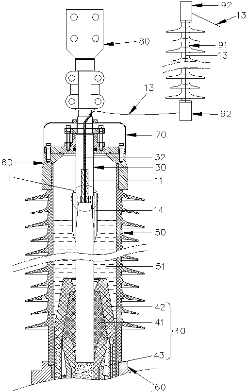
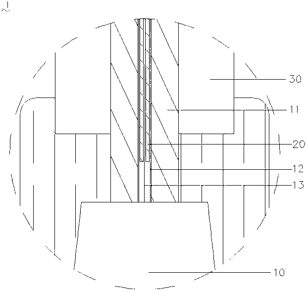
[0031] see figure 1 and figure 2 , 110kV and above cable terminal accessories of the present invention relate to oil-filled cable terminal accessories, which are used to connect cables 10 to electrical equipment (not shown in the figure), including at least one crimping liner 20, a connecting piece 30, and a stress control body 40. Insulating sleeve 50, two mounting flanges 60, shielding cover 70, outlet fittings 80, insulator 91 and optical fiber splice box 92.
[0032] The cable 10 includes a cable conductor 11 , an optical fiber sheath 12 disposed in the cable conductor 11 , and at least one optical fiber 13 sheathed in the optical fiber sheath 12 .
[0033] The crimped liner 20 may consist of one segment or several segments.
[0034] Preferably, the crimping liner 20 is made of a hard metal crimping liner, or a hard polymer material.
[0035] One end of the wiring member 30 is provided with a wiring hole 31 and an optical fiber outlet hole 32 , and the optical fiber ou...
Embodiment 2
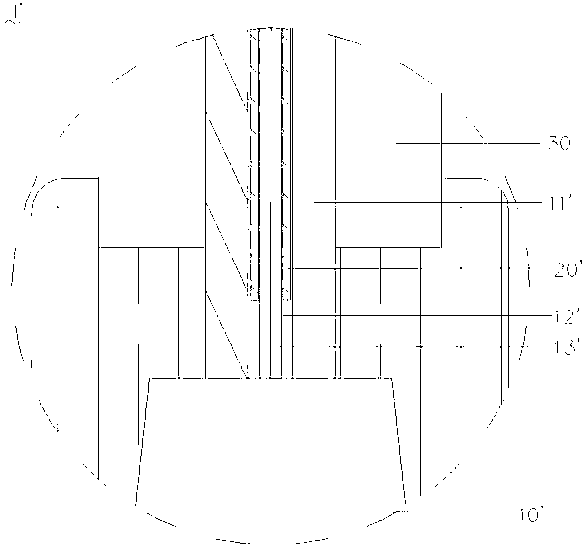
[0045] see image 3 , image 3 is the enlarged schematic diagram of I', where the position of I' is the same as figure 1 The position at I is the same, which discloses an embodiment in which the crimping liner is arranged inside the cable conductor and outside the fiber sheath. This embodiment is similar to Example 1, the difference being that the crimping liner 20' is set on The cable conductor 11' is located outside the optical fiber jacket 12', and the crimp liner 20' is indirectly located outside the optical fiber 13'. The optical fiber 13' of the cable 10 is led out from one end of the optical fiber sheath 12'.
[0046] The 110kV and above cable terminal accessories of the present invention are equipped with a crimping liner 20' outside the optical fiber sheath 12' of the cable conductor 11', and the optical fiber 13' of the cable 10' comes out from one end of the optical fiber sheath 12' and is drawn out through the optical fiber outlet hole 32. And connected with the...
Embodiment 3
[0048] see Figure 4 , Figure 4 It is the enlarged schematic diagram of I'', where the position of I'' is the same as figure 1 The position at I is the same, which discloses Embodiment 3 of the cable terminal accessories of 110kV and above in the present invention. This embodiment is similar to Embodiment 1, the difference is that: the cable conductor 11'' is located outside the optical fiber sheath 12 further A crimping liner 20 ″ is provided, and the crimping liner 20 ″ is indirectly located outside the optical fiber 13 .
[0049] The 110kV and above cable terminal accessories of the present invention are provided with a crimping liner 20 inside the optical fiber sheath 12 of the cable conductor 11'', and a crimping liner 20'' is set outside the optical fiber sheath 12, and between the connector 30 and the cable conductor 11 When crimping the connection, the crimping liner 20 / 20'' bears the crimping force, which prevents the optical fiber 13 in the crimping liner 20 / 20'' ...
PUM
 Abstract
Description
Claims
Application Information
 - R&D Engineer
- R&D Manager
- IP Professional
- Industry Leading Data Capabilities
- Powerful AI technology
- Patent DNA Extraction
Browse by: Latest US Patents, China's latest patents, Technical Efficacy Thesaurus, Application Domain, Technology Topic, Popular Technical Reports.
© 2024 PatSnap. All rights reserved.Legal|Privacy policy|Modern Slavery Act Transparency Statement|Sitemap|About US| Contact US: help@patsnap.com