
Miniaturization short wave broadband omnidirectional high elevation communication antenna

A communication antenna and high-elevation-angle technology, applied in the field of short-wave communication, can solve the problems of long size, need, and low communication rate, and achieve the effects of stable radiation pattern, simple antenna structure, and easy production.

Inactive Publication Date: 2013-08-28
THE 22ND RES INST OF CHINA ELECTRONICS TECH GROUP CORP
View PDF4 Cites 6 Cited by
  • Summary
  • Abstract
  • Description
  • Claims
  • Application Information

AI Technical Summary

Problems solved by technology

The disadvantages are: the size is long, the antenna body is generally about 30 meters to 40 meters long, and a support rod is required, the communication distance is related to the height, directional communication, and not omnidirectional
The disadvantages are: the efficiency is too low, the pass rate is low, it is not omnidirectional, the reliability is poor at low frequencies, and there is a dead point in the tuner

Method used


Image

  • Miniaturization short wave broadband omnidirectional high elevation communication antenna
  • Miniaturization short wave broadband omnidirectional high elevation communication antenna
  • Miniaturization short wave broadband omnidirectional high elevation communication antenna

Examples


Embodiment 1

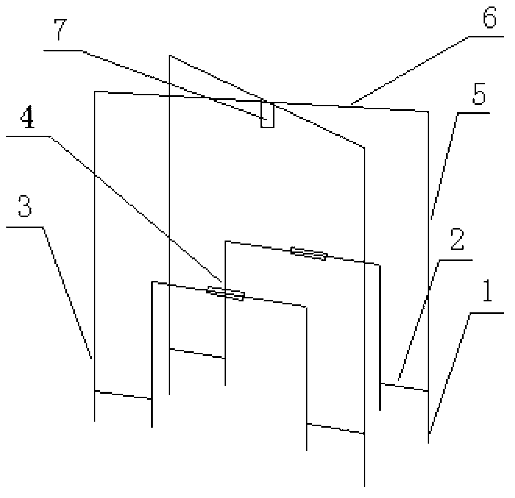
[0041] Example 1, such as figure 1 As shown, this embodiment discloses a miniaturized short-wave broadband omnidirectional high-elevation angle communication antenna, which includes eight bases 1 in two rows and four columns, and the adjacent outer and inner bases in each row are connected by transverse oscillators I2 , each base is equipped with a vertical vibrator I3, for the four vertical vibrators I on the inner side, connect the resistance-loaded load assembly 4 between the vertical vibrator I in the same line, and for the four vertical vibrator I on the outer side, Then continue to install the vertical vibrator II5 on it, between the four vertical vibrators II, two horizontal vibrators II6 are installed crosswise, and the impedance converter 7 is installed at the intersection of the horizontal vibrators II.

Embodiment 2

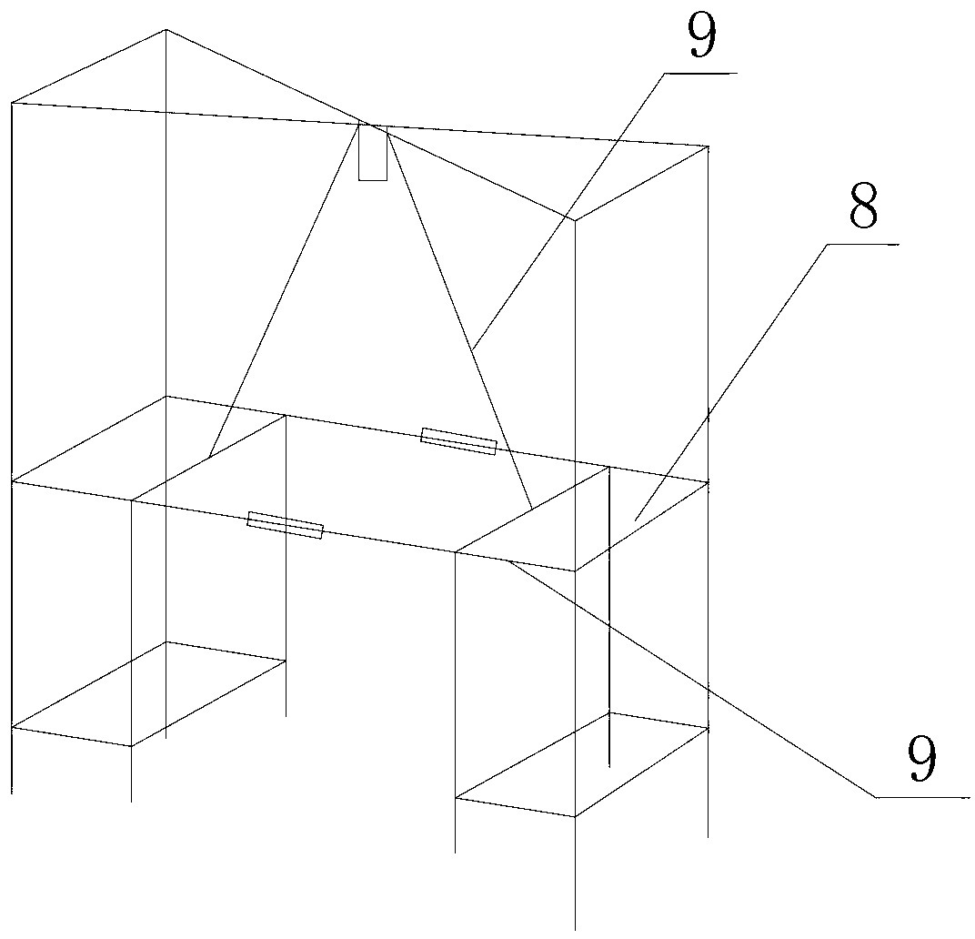
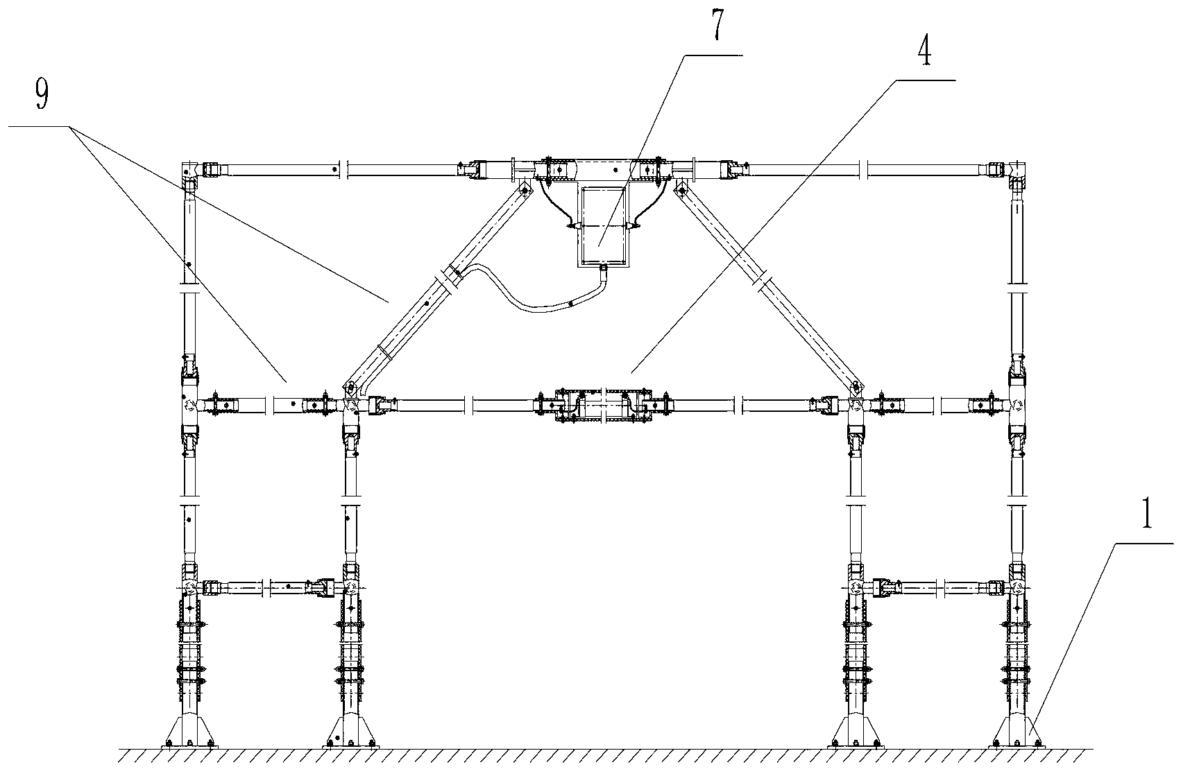
[0042] Example 2, such as Figure 2-4 As shown, in this embodiment, on the basis of Embodiment 1, a metal support 8 is installed between the vertical vibrators 1 of each column, and an insulating support 9 is installed between the vertical vibrators 1 on the outer and inner sides of each row. An insulating support 9 is also installed between the lateral vibrator II and the inner metal support, and multiple metal supports and insulating supports can be provided as required.

[0043] like Figure 5 As shown, the base is composed of a steel support seat and an insulating pipe. The steel support seat is welded by seamless steel pipes, reinforcing ribs and a bottom plate. The insulating pipe is connected to the steel support seat with bolts.

[0044] like Image 6 As shown, the load assembly includes resistors, insulating joints, aluminum joints and vibrators. The insulating joints are also used as the box cover for the resistors. The aluminum joints are used to connect the insul...


PUM


Abstract

The invention discloses a miniaturization short wave broadband omnidirectional high elevation communication antenna which comprises eight bases which are arranged into two rows and four columns, each two bases which are arranged in the same row and on the outer side and the inner side respectively are connected with each other through a transverse vibrator I, and each base is provided with a vertical vibrator I. Load assemblies for resistance loading are arranged among the four vertical vibrators I which are arranged on the inner side and in the same row, the four vertical vibrators I which are arranged on the outer side and in the same row are continuously provided with vertical vibrators II, two transverse vibrators II are arranged among each four vertical vibrators II in a cross mode, and impedance transformers are arranged on cross points of the transverse vibrators II. The antenna is simple in structure, convenient to produce, small in size, and capable of being conveniently supported in a small place, achieves a high elevation of a radial direction picture when at low and medium frequency, is suitable for middle-near distance communication, achieves a low elevation of the radial direction picture when at high frequency, can meet communication requirements of a remote distance, and meanwhile meets communication requirements of remote, middle and near distances.

Description

technical field [0001] The invention relates to the technical field of short-wave communication, in particular to a miniaturized short-wave broadband omnidirectional high-elevation angle communication antenna in this field. Background technique [0002] Although the modern communication technology is very complete, the traditional short-wave communication still has its irreplaceable advantages, and the short-wave antenna is a necessary equipment for short-wave communication. The performance of the antenna largely determines the performance of the communication system. Although human technology is changing with each passing day, there has been no major progress in short-wave antenna technology for decades. The conflicts between the large geometric size, high gain, omnidirectionality, and radiation elevation angle of the short-wave antenna are difficult to be resolved or well balanced. [0003] Brief introduction and comparison of advantages and disadvantages of commonly use...

Claims


Application Information

Patent Timeline
Patent Type & Authority Applications(China)
IPC IPC(8): H01Q1/36H01Q1/12
Inventor 王海何绍林秦晋平李虎李建刚宋晓远
Owner THE 22ND RES INST OF CHINA ELECTRONICS TECH GROUP CORP
Learn More