Carbon substance pyrolysis method and carbon substance vibration pyrolysis tower
A carbon material, pyrolysis technology, applied in the field of coal chemical industry, can solve the problems of lignite cracking and other problems
- Summary
- Abstract
- Description
- Claims
- Application Information
AI Technical Summary
Problems solved by technology
Method used
Image
Examples
Embodiment 1
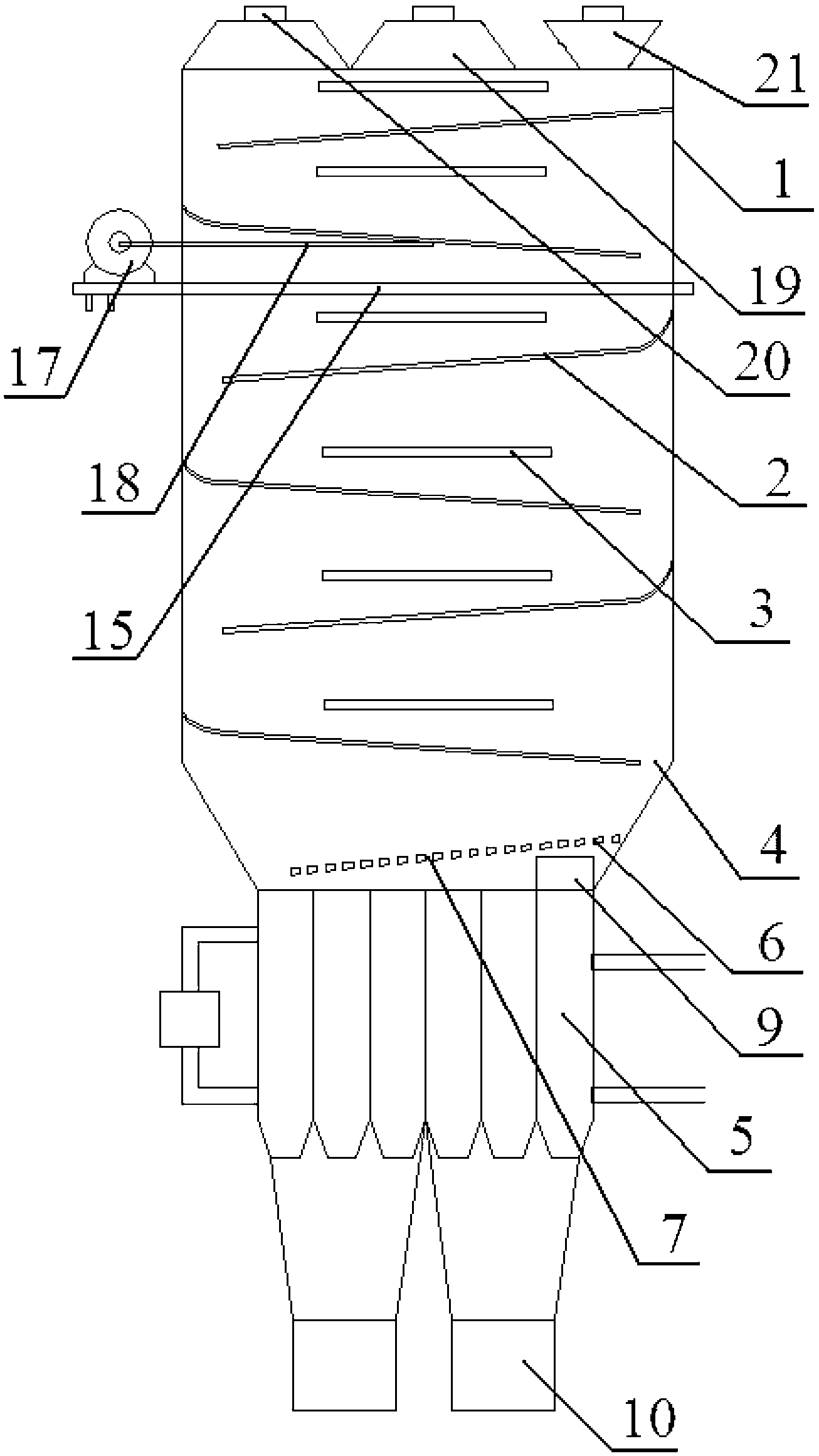
[0030] figure 1 It is a structural schematic diagram of a carbon material vibrating pyrolysis tower provided by Embodiment 1 of the present invention. The carbon material vibrating pyrolysis tower provided by the present invention comprises: casing 1, at least five vibrating beds 2, radiant tubes 3 with adjustable heating temperature; the inside of said casing 1 is isolated from the outside air; at least five of said The vibrating beds 2 are arranged in a zigzag from top to bottom in the casing 1; each vibrating bed 2 is provided with a feeding port 4; each vibrating bed 2 is provided with the The radiant tube 3; the heating temperature of the radiant tube 3 increases from top to bottom; wherein, the heating temperature of the radiant tube 3 at the bottom layer is 600°C-750°C.
[0031] In the carbon material vibrating pyrolysis tower provided in the first embodiment, in the coal pyrolysis device provided above in the present invention, the carbon material vibrating pyrolysis ...
Embodiment 2
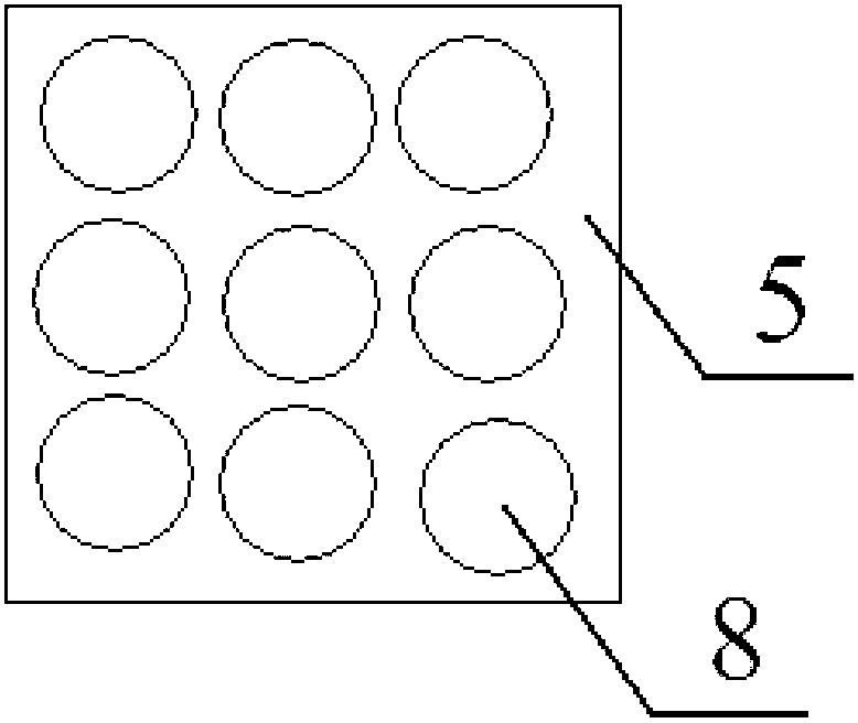
[0033] see figure 1 as well as figure 2 As shown, on the basis of the first embodiment above, the carbon material vibration pyrolysis tower provided by the second embodiment of the present invention also includes a water cooling jacket 5 and a distributor 6; the distributor 6 is located at the bottom of the vibration Below the feeding port 4 of the bed 2, and arranged in a zigzag shape with the vibrating bed 2 on the lowermost floor; the distributor 6 is provided with a plurality of lower leakage holes 7; the water cooling jacket 5 is located in the distribution 6, and a plurality of cooling passages 8 extending in the vertical direction are formed in the water cooling jacket 5; Sweeper 9 with surface movement.
[0034] In this second example, since the temperature of coal can reach 300°C-750°C during pyrolysis, in order to prevent the semi-coked coal generated after coal pyrolysis from burning at this temperature, the semi-coked coal generated by coal pyrolysis needs to be...
Embodiment 3
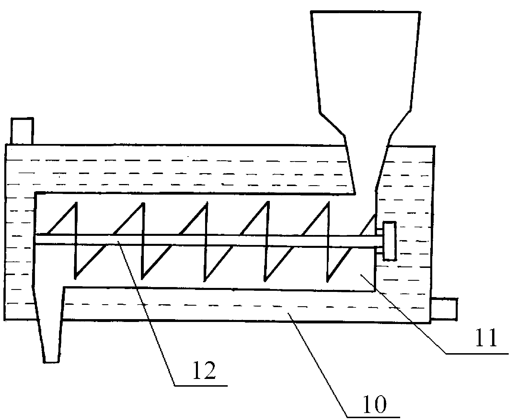
[0039] figure 1 and image 3 It is a structural schematic diagram of the carbon material vibrating pyrolysis tower provided by Embodiment 3 of the present invention. On the basis of the above-mentioned embodiment two, see figure 1 as well as image 3 As shown, in the carbon material vibrating pyrolysis tower provided in the third embodiment, a water-cooled box 10 is also included; a water-cooled chamber 11 is formed in the water-cooled box 10 to communicate with the cooling passage 8 and the outside world; the water-cooled A screw pusher 12 for pushing coal to the outside is also arranged in the chamber 11 .
[0040] In the third embodiment, since the temperature of the semi-coked coal needs to be rapidly reduced to below the ignition point of the semi-coked coal during the cooling process, in order to increase the cooling rate of the semi-coked coal, a carbon vibrating pyrolysis tower is added Water cooling box 10. The water-cooled box 10 forms a water-cooled chamber 11 ...
PUM
 Abstract
Description
Claims
Application Information
 - R&D
- Intellectual Property
- Life Sciences
- Materials
- Tech Scout
- Unparalleled Data Quality
- Higher Quality Content
- 60% Fewer Hallucinations
Browse by: Latest US Patents, China's latest patents, Technical Efficacy Thesaurus, Application Domain, Technology Topic, Popular Technical Reports.
© 2025 PatSnap. All rights reserved.Legal|Privacy policy|Modern Slavery Act Transparency Statement|Sitemap|About US| Contact US: help@patsnap.com


