Battery system with cell voltage detecting units

A battery system and unit voltage technology, which is applied in the field of battery systems, can solve problems such as battery system failures, and achieve the effects of avoiding subsequent damage and facilitating inspection

Active Publication Date: 2013-08-21
ROBERT BOSCH GMBH +1
View PDF4 Cites 0 Cited by
  • Summary
  • Abstract
  • Description
  • Claims
  • Application Information

AI Technical Summary

Problems solved by technology

However, if these values ​​are wrong, then it can lead to faulty behavior of the entire battery system

Method used


Image

  • Battery system with cell voltage detecting units
  • Battery system with cell voltage detecting units
  • Battery system with cell voltage detecting units

Examples


Embodiment Construction

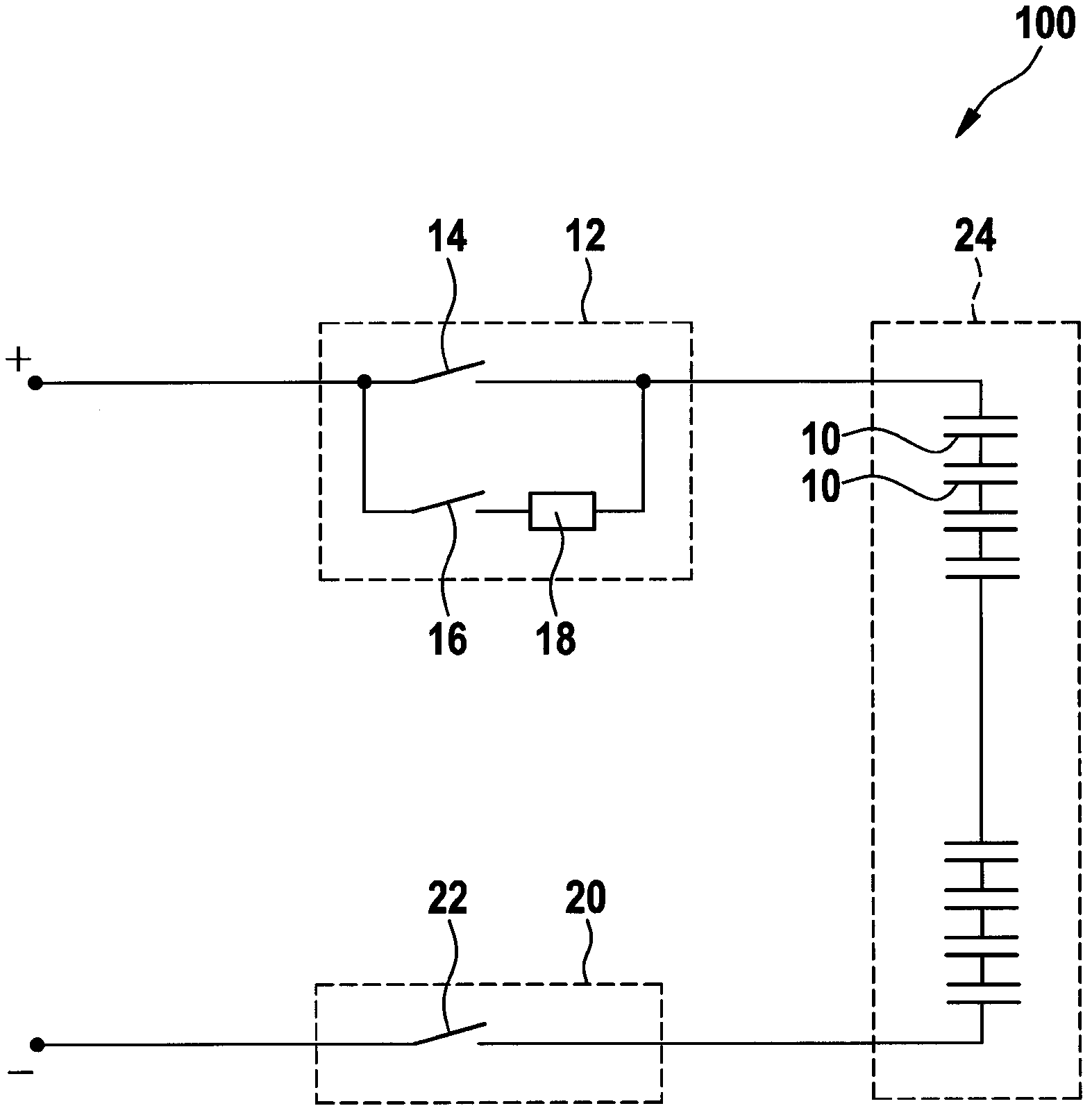
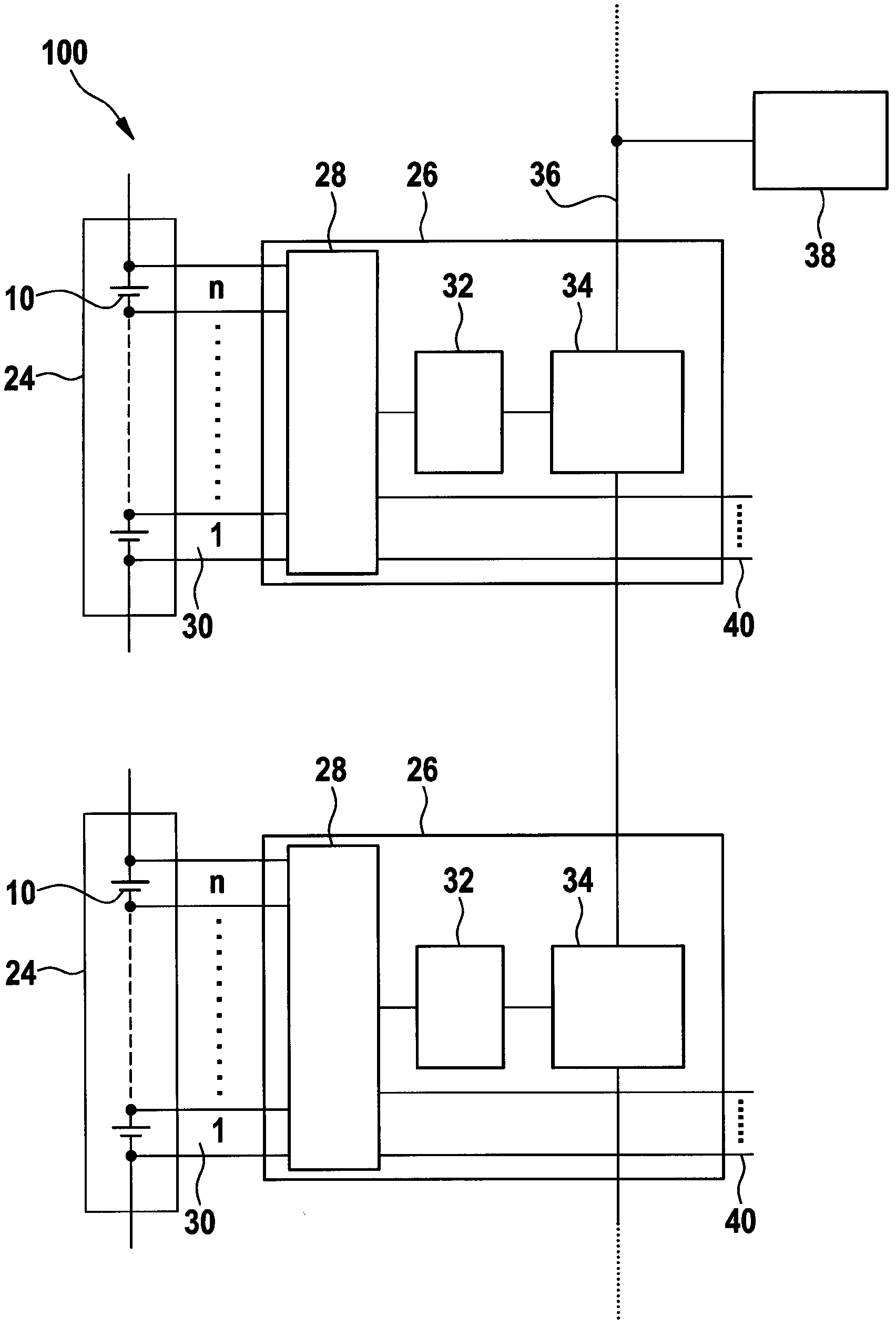
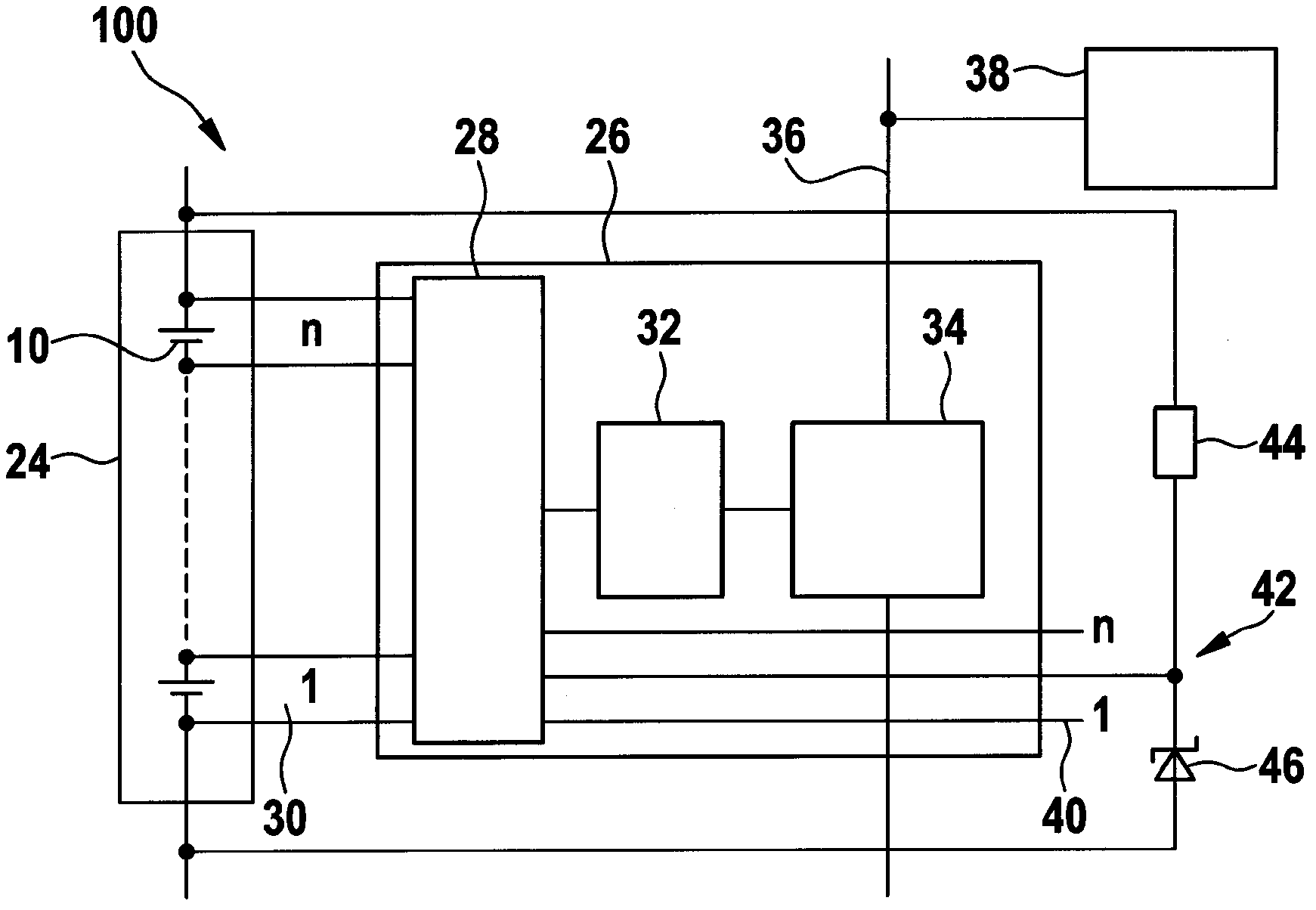
[0023] image 3 A battery system 100 according to a first embodiment of the invention is shown. Several battery cells 10 are connected in series and integrated in a module 24 . The cell voltages of the individual battery cells 10 are collected in a multiplexer 28 and fed into a communication bus 36 via an analog-to-digital converter 26 and a gateway 34 . The voltage evaluation is carried out by the microcontroller 38 in a known manner.

[0024] Furthermore, one auxiliary connection 40 of the auxiliary connections of the multiplexer 28 is supplied with a constant auxiliary voltage. This constant auxiliary voltage is provided via a circuit arrangement 42 which also includes a resistor 44 and a Zener diode 46 . A constant voltage of, for example, 2.5 V is thus tapped via the module 24 and applied to the auxiliary connection 40 of the multiplexer 28 . This auxiliary voltage is likewise supplied to the communication bus 36 and thus to the microcontroller 38 via the unit voltage...


PUM


Abstract

The invention relates to a battery system (100) with at least one module (24) that comprises a plurality of battery cells (10). A cell voltage detecting circuit is associated with each battery cell (10). The cell voltage detecting circuits of a module (24) are connected to a multiplexer (28). An output of the multiplexer (28) is connected to a communication bus via an analog-digital converter (32), said communication bus being connected to an evaluating unit. The multiplexer (28) is additionally connected to at least one auxiliary voltage source that is known to the evaluating unit. The invention further relates to a method for monitoring a battery system with at least one module comprising a plurality of battery cells. A voltage of each of the battery cells is detected and fed to an evaluating unit via a cell voltage detecting unit, an output signal of the cell voltage detecting unit being tested for plausibility. A motor vehicle with a battery system (100) is provided, said battery system (100) being connected to a drive system of the motor vehicle.

Description

technical field [0001] The invention relates to a battery system, a method for monitoring a battery system and a motor vehicle having a battery system according to the invention. Background technique [0002] In the future, more and more new types of battery systems will be used, both in static applications and in vehicles such as hybrid vehicles and electric vehicles, and high requirements are placed on the reliability of such battery systems. [0003] The background to this high demand is that failure of the battery system can lead to failure of the entire system. In electric vehicles, for example, failure of the traction battery can lead to so-called "squatting". In addition, the failure of the battery can also cause safety-related problems. In wind power plants, for example, batteries are used in order to protect the plant from impermissible operating states in strong winds by means of blade control. [0004] The schematic circuit diagram of the storage battery system...

Claims


Application Information

Patent Timeline
Patent Type & Authority Applications(China)
IPC IPC(8): H01M10/42H01M10/48G01R31/36
CPCH01M10/4285H01M10/482G01R31/3835G01R31/396Y02E60/10H01M10/48G01R31/3648H02J7/0014H01M10/425H02J7/0016G01R31/382
Inventor S·布茨曼
Owner ROBERT BOSCH GMBH
Why Eureka
Try Eureka