Internal combustion engine fuel delivery system with rotary pump
A fuel delivery and rotary pump technology, applied in rotary piston pumps, rotary piston machines, liquid fuel engines, etc., can solve problems such as failure, achieve simple cost, low cost, and reduce operating noise and pressure pulsation.
- Summary
- Abstract
- Description
- Claims
- Application Information
AI Technical Summary
Problems solved by technology
Method used
Image
Examples
Embodiment Construction
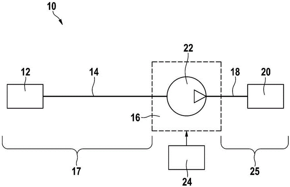
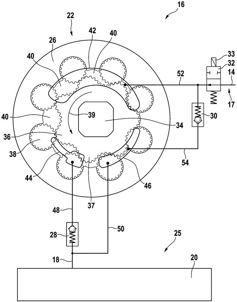
[0030] figure 1A very simplified schematic diagram of a fuel system 10 of an internal combustion engine, not shown here, is shown. From left to right in the drawing, a fuel tank 12 is connected to a fuel delivery system 16 via a low-pressure line 14 . The region upstream of fuel delivery system 16 corresponds to low-pressure region 17 . Furthermore, a high-pressure accumulator 20 (“common rail”) is coupled to the fuel delivery system 16 via a high-pressure line 18 . The fuel delivery system 16 includes a rotary pump 22 which can be controlled by a control and / or regulating device 24 of the internal combustion engine. The downstream region of fuel delivery system 16 corresponds to high-pressure region 25 .
[0031] During operation, the rotary pump 22 delivers fuel from the fuel tank 12 into the high-pressure accumulator 20 . From this high-pressure accumulator, fuel can be injected into the combustion chamber of the internal combustion engine by means of an injection valve...
PUM
 Abstract
Description
Claims
Application Information
 - R&D
- Intellectual Property
- Life Sciences
- Materials
- Tech Scout
- Unparalleled Data Quality
- Higher Quality Content
- 60% Fewer Hallucinations
Browse by: Latest US Patents, China's latest patents, Technical Efficacy Thesaurus, Application Domain, Technology Topic, Popular Technical Reports.
© 2025 PatSnap. All rights reserved.Legal|Privacy policy|Modern Slavery Act Transparency Statement|Sitemap|About US| Contact US: help@patsnap.com


