
Slide rail device for vehicle

A technology of sliding rails and rails, which is applied to special positions of vehicles, vehicle seats, vehicle parts, etc., and can solve the problem that the locking lever cannot be released.

Inactive Publication Date: 2013-08-21
SHIROKI KOGYO CO LTD
View PDF4 Cites 6 Cited by
  • Summary
  • Abstract
  • Description
  • Claims
  • Application Information

AI Technical Summary

Problems solved by technology

[0009] On the other hand, this problem can be solved by making the lock groove longer, etc., so that the lock lever cannot be released from the lock groove unless the operation lever is rotated largely upward.

Method used


Image

  • Slide rail device for vehicle
  • Slide rail device for vehicle
  • Slide rail device for vehicle

Examples


Embodiment Construction

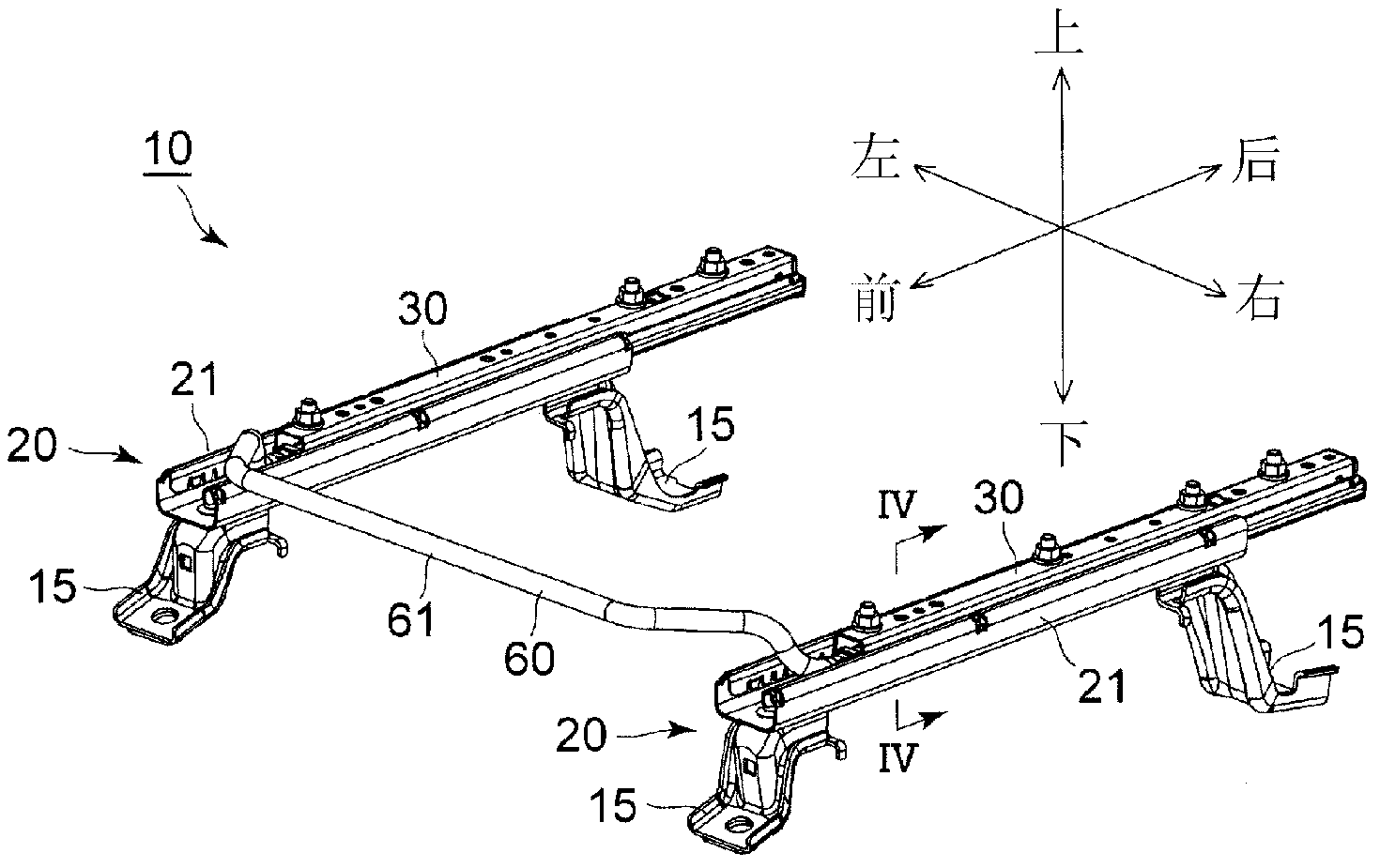
[0108] Hereinafter, a first embodiment of the present invention will be described with reference to the drawings. In addition, the directions in the following description are based on the arrowed line directions described in the drawings.

[0109] The slide rail device 10 is installed on an interior floor surface of an automobile (vehicle) not shown, and a seat (not shown) is fixed to the upper surface of the slide rail device 10 (upper rail 30 ).

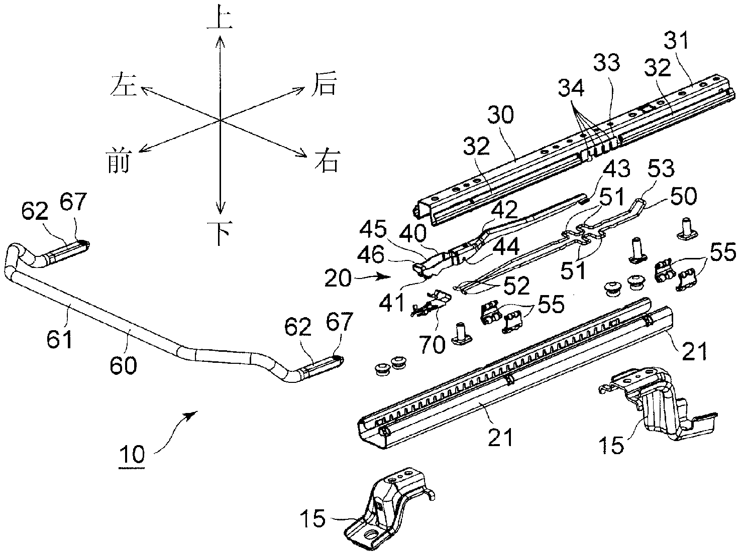
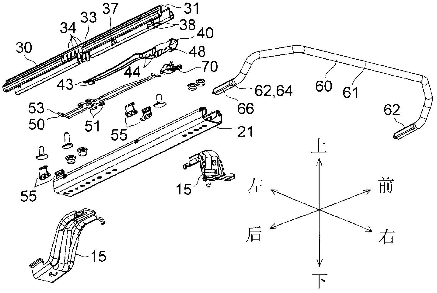
[0110] Next, the detailed structure of the slide rail apparatus 10 is demonstrated.

[0111] The slide rail device 10 includes a pair of left and right rail units 20 and a ring handle 60 connecting front ends of the left and right rail units 20 as major components. Since the left and right rail units 20 are bilaterally symmetrical to each other, and the ring handle 60 has a bilaterally symmetrical shape, the slide rail device 10 as a whole is bilaterally symmetrical.

[0112] The left and right rail units 20 are structured as fol...


PUM


Abstract

Provided is a slide rail device for a vehicle which, even if the range in which a lock operation lever can be rotated is restricted to a narrow range by an upper rail, is capable of increasing the range in which a handle connected to the lock operation lever can be rotated, and is capable of reducing the operating force required for unlocking. The slide rail device for a vehicle is provided with: a rotatable lock operation lever (40) disposed in a space inside an upper rail (30); an upper support part (46) disposed on the lock operation lever; a handle (60) having a lower supported part (65) on the bottom surface, supported so as to be able to rotate relative to a lower support part, and an upper supported part (66) on the top surface, supported so as to be able to rotate relative to an upper support part; and an impelling means (70) for rotationally impelling the handle relative to the lock operation lever in a direction in which the state in which the lower supported part is supported by the lower support part, and the state in which the upper supported part is supported by the upper support part are constantly maintained.

Description

technical field [0001] The present invention relates to a slide rail device for a vehicle that slidably supports a seat. Background technique [0002] The sliding rail device for vehicles in Patent Document 1 includes: a pair of left and right lower rails, which extend in the front-rear direction and are fixed to the floor surface of the vehicle interior, and have a plurality of locking grooves arranged in the front-rear direction; a pair of left-right upper rails, a support seat The seat part of the chair is slidably supported by the left and right lower rails; the left and right pair of lock levers are rotatably supported by the left and right upper rails around the axis in the left and right directions, and can be engaged with / disengaged from the lock grooves. The part of the upper part is arranged in the inner space of the upper rail; the force application part is arranged in the inner space of the upper rail, and rotates and applies force in the direction of making the ...

Claims


Application Information

Patent Timeline
Patent Type & Authority Applications(China)
IPC IPC(8): B60N2/08
CPCB60N2/0705B60N2/0715B60N2/0818B60N2/0875B60N2/0887B60N2205/20B60N2/0881B60N2/08
Inventor 林直树
Owner SHIROKI KOGYO CO LTD
Learn More