Multifunctional vehicle-borne battery box
A vehicle-mounted battery box, multi-functional technology, applied in the direction of secondary batteries, battery pack components, circuits, etc.
- Summary
- Abstract
- Description
- Claims
- Application Information
AI Technical Summary
Problems solved by technology
Method used
Image
Examples
Embodiment 1
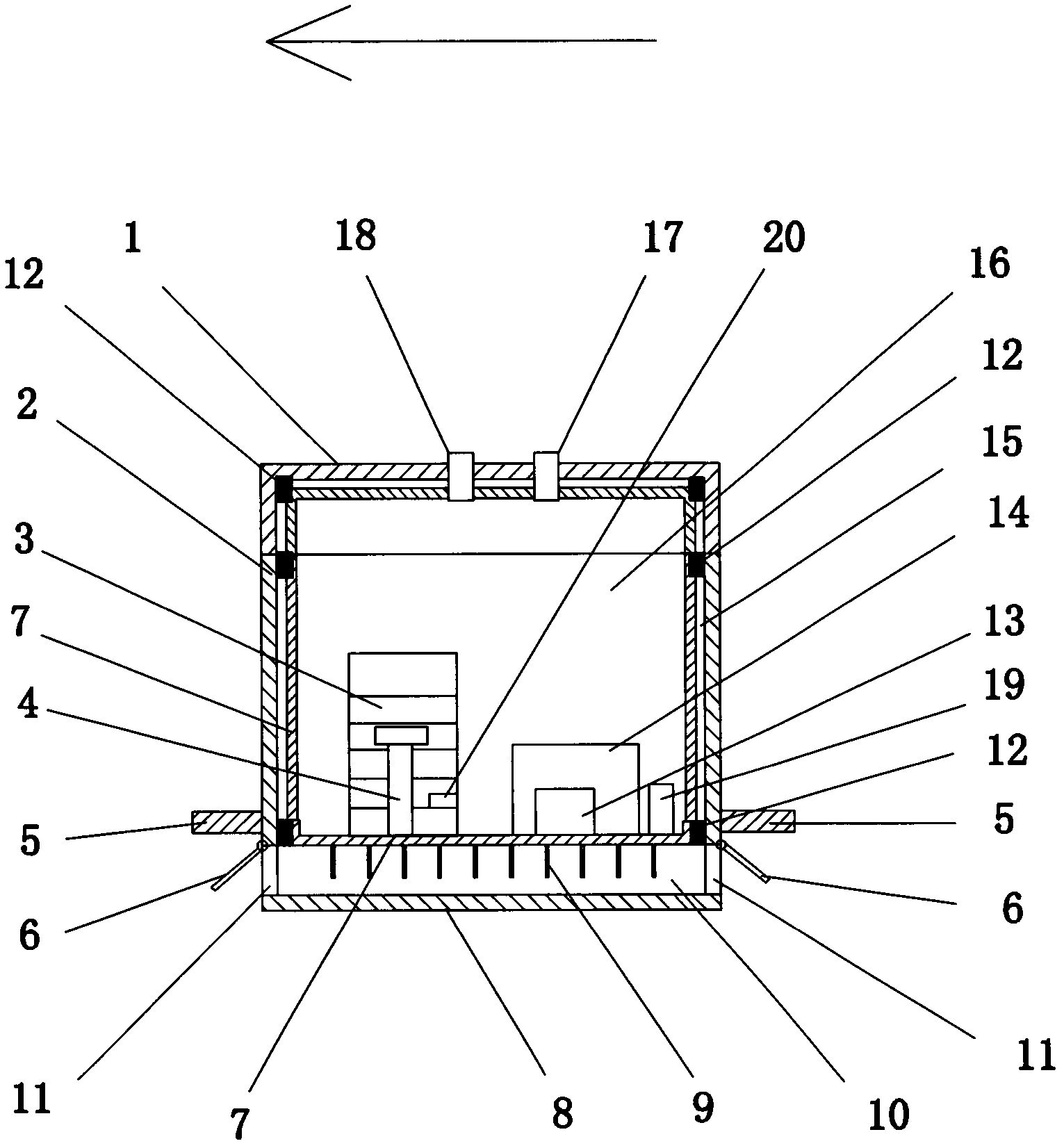
[0023] like figure 1 The battery box shown is used to be installed at the bottom of the car, and includes a box cover 1 , a box body 2 , a connecting body 5 and a battery pool system 3 . The connecting body 5 is equipped with bolts (not shown in the figure), which are used to connect the battery box with the vehicle body. The bottom of the battery box is made of a hollow clamping wall structure composed of an inner wall 7 and an outer wall 8. The inner wall 7 is fixed and sealed with the box body 2 through a fixed body 12, and the battery box is divided into a box space 16 And two parts of the interwall space 10. The battery system 3 is installed on the inner wall 7 in the box space 16 . The box space 16 is not in communication with the sandwiched wall space 10 .
[0024] The connecting body 5 is located at a position corresponding to the boundary between the box space 16 and the clamping wall space 10, so that after the battery box is connected to the vehicle body through ...
Embodiment 2
[0030] like figure 2 The shown battery box is used to be mounted on the back of the car, and its difference from Embodiment 1 is that the bottom of the battery box and the back wall are both made of a hollow clamping wall structure composed of an inner wall 7 and an outer wall 8 . That is, the battery box includes two interwall spaces. After the battery box is connected with the vehicle body through the connecting body 5, except the bottom of the box, the wall surface at the back of the box is also exposed outside the vehicle body. The inner walls 7 of the two clamping walls are heat conduction walls made of metal materials. The two heat conduction walls are equipped with a metal heat dissipation plate 9 on one side of the interwall space. On the folder wall at the bottom of the battery box, there is an air intake hole in the direction of the car (the direction indicated by the arrow in the figure), that is, the ventilation hole 11 on the left side below the figure. On the...
Embodiment 3
[0033] like image 3The difference between the shown battery box and Embodiment 1 is that each wall of the battery box is a hollow clamping wall structure. Wherein the clamping wall at the bottom of the battery box is provided with a ventilation hole 11 to form a ventilation channel 10 . All the other walls are sealed and separated by the fixed body 12, so that they are not connected with the outside world, nor communicated with the air passage at the bottom. The fixed body 12 is made of a bolt damping connection part with a plastic sleeve, a spring and a rubber pad, and has the functions of buffering and heat insulation. The inner wall 7 of the battery box and the cooling fins 9 at the bottom are made of aluminum alloy, and the outer wall 8 is made of engineering plastics to reduce the weight of the whole box. Obviously, when the ventilation door 6 is closed, each clamping wall of the battery box in this example has the function of a heat insulating wall. And when the vent...
PUM
 Abstract
Description
Claims
Application Information
 - R&D
- Intellectual Property
- Life Sciences
- Materials
- Tech Scout
- Unparalleled Data Quality
- Higher Quality Content
- 60% Fewer Hallucinations
Browse by: Latest US Patents, China's latest patents, Technical Efficacy Thesaurus, Application Domain, Technology Topic, Popular Technical Reports.
© 2025 PatSnap. All rights reserved.Legal|Privacy policy|Modern Slavery Act Transparency Statement|Sitemap|About US| Contact US: help@patsnap.com


