
Hidden door closer

A door closer and hidden technology, applied in door/window accessories, multi-purpose hand tools, construction, etc., can solve the problems of damage to the door closer transmission mechanism and drive motor, increase measurement error, and high position accuracy, and achieve Reduce maintenance chances and costs, avoid larger gaps, and increase transmission efficiency

Active Publication Date: 2013-08-21
OUBAO SECURITY TECH
View PDF5 Cites 8 Cited by
  • Summary
  • Abstract
  • Description
  • Claims
  • Application Information

AI Technical Summary

Problems solved by technology

But this structure has many disadvantages, one is that this structure is bulky, and for hidden door closers, in order to be easily installed in the door or door frame, the smaller the door closer, the more beautiful, so the size of the door closer is very large. Important; the second is the low transmission efficiency, the external door closer requires a large rotational force, and the low transmission efficiency of the bevel gear will lead to a large driving load on the internal motor of the door closer, which greatly shortens the service life of the motor; the third The position accuracy of the assembly is high. Due to the influence of the connection structure of the gear mesh, the angle between the input shaft and the output shaft must be 90°, otherwise the gear mesh connection will be affected.
[0003] During the use of door closers, especially electric door closers, the motor on the door closer drives the input shaft to rotate, and the input shaft drives the output shaft to rotate, and it is inevitable that the door will open and close in violation of the normal automatic mode, or some Malicious or accidental man-made damage causes the output shaft to get stuck suddenly, which will seriously damage the transmission mechanism and drive motor of the door closer. After repeated damages, it is easy to affect the operation of the door closer and even cause damage to the door closer
[0004] Moreover, an instrument for measuring the rotation angle of the output shaft is often installed on the door closer. In the prior art, there will be a contact part between the output shaft rotation angle measuring instrument and the output shaft. Long-term measurement will cause the position of the contact part to shift, increasing the In order to reduce the measurement error, the door closer will deviate in the closing position, and if it is serious, it will not be able to close the door

Method used


Image

  • Hidden door closer
  • Hidden door closer
  • Hidden door closer

Examples


Embodiment Construction

[0028] The present invention will be further described below in conjunction with accompanying drawing:

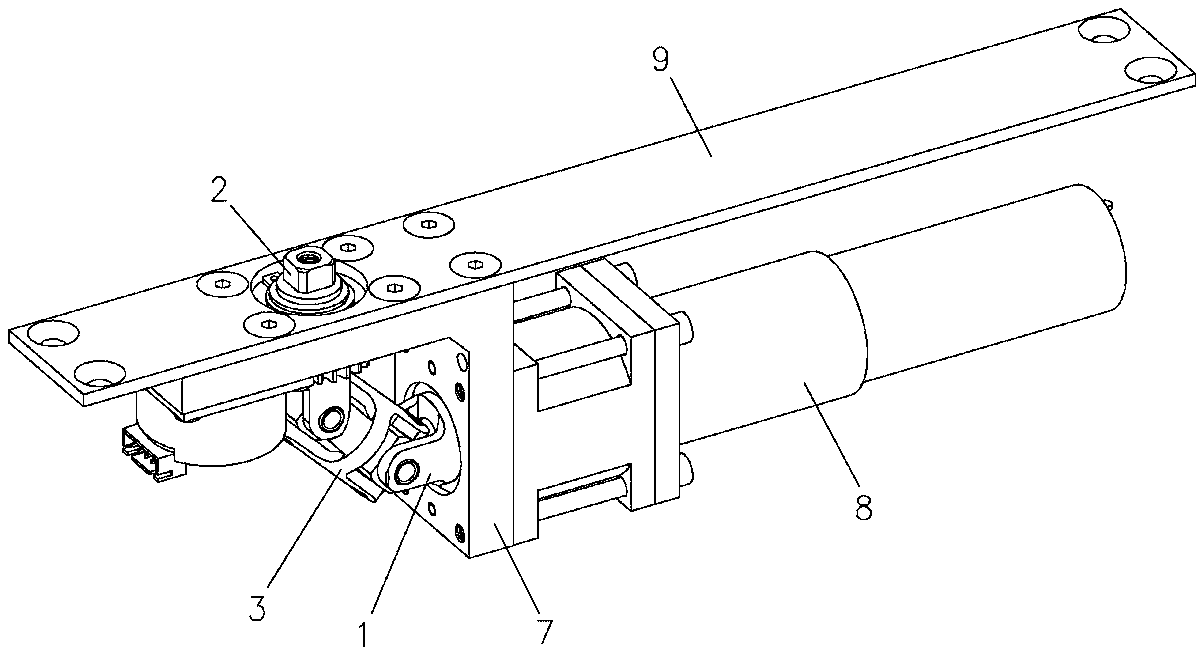
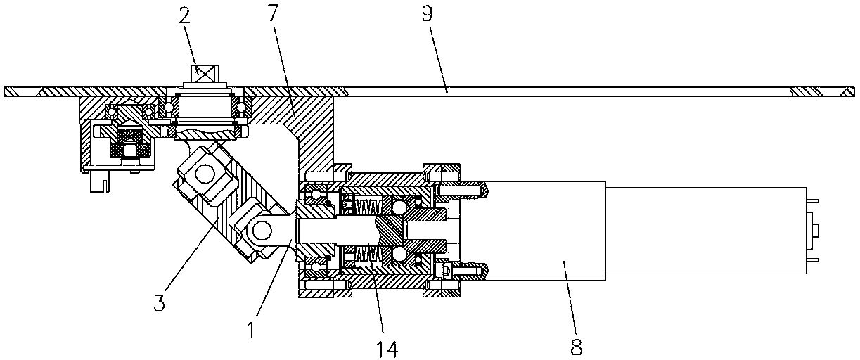
[0029] Referring to the accompanying drawings: this concealed door closer includes a housing 7, an input shaft 1 and an output shaft 2, the input shaft 1 is connected to a motor 8, and a connecting piece 3 is provided between the input shaft 1 and the output shaft 2, and the connecting piece The two ends of 3 are respectively provided with upper connecting piece 3-1 and lower connecting piece 3-2, and upper connecting piece 3-1 and lower connecting piece 3-2 are connected with roller 4 through vertical rotating shaft 5, wherein input shaft 1 and The output shaft 2 is respectively provided with a left connecting piece 1-1 and a right connecting piece 1-2, and the left connecting piece 1-1 and the right connecting piece 1-2 are laterally connected on the roller 4 through a transverse rotating shaft 6 .

[0030] Wherein the roller 5 is provided with a cross-shaped through hole...


PUM


Abstract

A hidden door closer comprises a casing, an input shaft and an output shaft. The input shaft is connected with a motor. A connecting component is arranged between the input shaft and the output shaft. An upper connecting piece and a lower connecting piece are arranged at two ends of the connecting component respectively. A roller is connected with the upper connecting piece and the lower connecting piece through a vertical rotating shaft. A left connecting piece and a right connecting piece are arranged on the input shaft and the output shaft respectively. The left connecting piece and the right connecting piece are horizontally connected with the roller through a horizontal rotating shaft. The components in the structure are simple in structure and convenient to process and assemble; size of a joint after assembly is equivalent to that of the connecting component, so that overall size is small. During transmission, the output shaft is directly driven the input shaft to rotate through the connecting component, and transmission efficiency is increased. A universal joint structure is employed in transmission connection between the input shaft and the output shaft. The transmission efficiency of the structure is high, the size is small, quality is excellent, cost is low, process is simple, precision is reliable, and the hidden door closer is beneficial to wide promotion.

Description

technical field [0001] The invention relates to a door closer, in particular to a concealed door closer. Background technique [0002] At present, the use of door closers is becoming more and more widely, especially some hidden door closers, which can be hidden in the door or door frame, and drive the rotation of the door through the hidden slide rail and rocker arm, retaining the original door beauty. The current technology is generally external, using gear meshing transmission to realize the transmission connection of 90° steering between the input shaft and the output shaft. But this structure has many disadvantages, one is that this structure is bulky, and for hidden door closers, in order to be easily installed in the door or door frame, the smaller the door closer, the more beautiful, so the size of the door closer is very large. Important; the second is the low transmission efficiency, the external door closer requires a large rotational force, and the low transmiss...

Claims


Application Information

Patent Timeline
Patent Type & Authority Applications(China)
IPC IPC(8): E05F15/12E05F15/611
CPCE05Y2201/636E05F15/614E05F15/63E05F15/603
Inventor 李豪杰伏振峰张茂陈王长连吴振波刘洪波
Owner OUBAO SECURITY TECH
Learn More