
A speed-limiting braking system for suspended elevators

A brake system and elevator technology, applied in elevators, transportation and packaging, etc., can solve the problems of complex inspection, maintenance and repair, wedges that cannot be reset, wedges that cannot be stuck on the guide rail, etc., to avoid long-distance control out of sync , to avoid failure, to avoid the effect of danger

Inactive Publication Date: 2015-09-09
HENAN UNIV OF SCI & TECH
View PDF8 Cites 0 Cited by
  • Summary
  • Abstract
  • Description
  • Claims
  • Application Information

AI Technical Summary

Problems solved by technology

[0004] 2. Due to the change and extension of the wire rope itself, the tensioning device touches the ground, so that the tension of the wire rope is not enough and slipping occurs;
[0005] 3. The transmission part of the connecting rod arm of the safety gear is short of oil and corroded, causing the lifting force to greatly exceed the preset force;
[0006] 4. The distance between the end of the active lever and the linkage switch of the safety gear is too large. When the pull arm is lifted, the switch cannot act at the same time;
[0007] 5. The gap between the wedge and the side working surface of the guide rail is too large. When the connecting rod is lifted, the wedge cannot hold the guide rail;
[0008] 6. There is too much oil in the wedge, and the wedge cannot be reset after the pull arm is released, causing damage to the guide rail
[0009] 7. Inspection, maintenance and repair are complicated, and potential problems are not easy to be found in time
[0010] The existence of these problems not only makes the system a decoration, but also easily paralyzes people's minds, and the potential harm is even greater

Method used


Image

  • A speed-limiting braking system for suspended elevators

Examples


Embodiment Construction

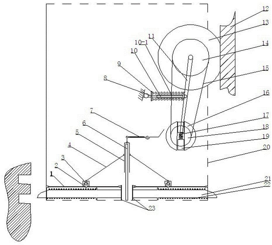
[0022] As shown in the figure, the specific implementation method is as follows:

[0023] A speed-limiting brake system for hanging elevators, including a bracket 20, a speed control system and a brake system, the speed control system and the brake system are all installed on the bracket 20,

[0024] The speed control system includes a friction wheel 13, a large pulley 14, a small pulley 18, a connecting shaft 11, a pressure lever mechanism and an active lever mechanism. The friction wheel 13 is coaxially arranged with the large pulley 14, and the large pulley 14 and the small pulley 18 are rotated and arranged at the two ends of the connecting shaft rod 11, the connecting end of the small pulley 18 and the connecting shaft rod 11 is fixed on the support 20, the large pulley 14 and the small pulley 18 are linked by the belt 15, and the pressure bar mechanism is pressed on the connecting rod. On the shaft 11, the friction wheel 13 is attached to the elevator channel 12. The act...


PUM


Abstract

Provided is a speed-limiting braking system for a hanging elevator. The speed-limiting braking system for the hanging elevator comprises a support, a speed control system and a braking system. The speed control system and the braking system are both mounted on the support. The speed control system adopts a centrifugal pin to work under the action of centrifugal force and drives the braking system to run when speed exceeds limited speed. According to the speed-limiting braking system for the hanging elevator, the speed control system and the braking system are both directly arranged on the support of an elevator box body, the defect that the remote control of a speed governor and the remote control of a safety gear cannot be synchronous and timely is avoided, and the defect that the speed governor and the safety gear are out of operation is avoided. The speed-limiting braking system for the hanging elevator is sensitive in triggering, safe and reliable, if only the speed exceeds a preset safety value, the elevator is made to be stopped, and when a set spring is out of operation, the support ejects out the centrifugal pin, the braking system is turned to jam the elevator to stop running, and danger is prevented from occurring.

Description

technical field [0001] The invention relates to a speed control device for a suspended elevator, in particular to a speed-limiting braking system for a suspended elevator. Background technique [0002] At present, elevator safety mainly consists of speed limiter and safety gear to form an elevator safety system. The speed limiter is the safety protection device of the elevator. It monitors and controls the speed of the car at any time. When the speed exceeds 115% of the rated speed of the elevator, it can send a signal in time, and then generate a mechanical action to cut off the power supply circuit. Tractor braking. If the elevator is still unable to brake, the safety gear installed at the bottom of the car will force the car to stop. The elevator safety gear device is under the control of the speed limiter. When the speed of the elevator exceeds the limit speed set by the speed limiter, or when the suspension rope breaks and relaxes, it will stop the car in an emergency...

Claims


Application Information

Patent Timeline
Patent Type & Authority Patents(China)
IPC IPC(8): B66B5/26B66B5/04
Inventor 李玉柱马磊高吭罗四倍
Owner HENAN UNIV OF SCI & TECH
Learn More