
Automatic rice steamer filling machine with rotatory center

A rotary device, automatic technology, applied in the directions of transportation and packaging, loading/unloading, etc., can solve the problems of large human factors, high falling height of materials, and many mechanical movements, so as to overcome the influence of human factors, improve work efficiency, and improve the falling height. consistent effect

Inactive Publication Date: 2013-08-21
黄先全
View PDF9 Cites 12 Cited by
  • Summary
  • Abstract
  • Description
  • Claims
  • Application Information

AI Technical Summary

Problems solved by technology

At present, some domestic manufacturers have developed mechanized retort loading equipment, but because of the complexity of the retort loading equipment and too many mechanical actions, automatic production cannot be realized, and there are problems such as inconvenient use and maintenance, so it has not been widely used.
Sichuan Yibin Minjiang Machinery Manufacturing Co., Ltd. applied for a Chinese invention patent on November 30, 2010, "a semi-automatic steamer device for solid-state brewing and grain grains", the publication number is CN102070025A, and the manual discloses a semi-automatic steamer that can reduce the labor intensity of the operator. The upper retort device, which uses the conveying channel to transport the grain grains, and a breaking device is installed in the conveying channel, the conveying channel moves up and down relative to the vertical axis, moves back and forth and rotates, and the movement track of the feeding port is realized by the worker manually operating the handle, and the movement accuracy And the degree of coherence depends on the skill of the operator. The human factor is large, and the discharge port cannot be extended into the retort. When the bottom layer is loaded, the material falls too high, there is a risk of stepping on the steam, and the quality of the retort is unstable; only semi-automatic Retort, can not achieve full automatic control

Method used


Image

  • Automatic rice steamer filling machine with rotatory center
  • Automatic rice steamer filling machine with rotatory center

Examples


Embodiment Construction

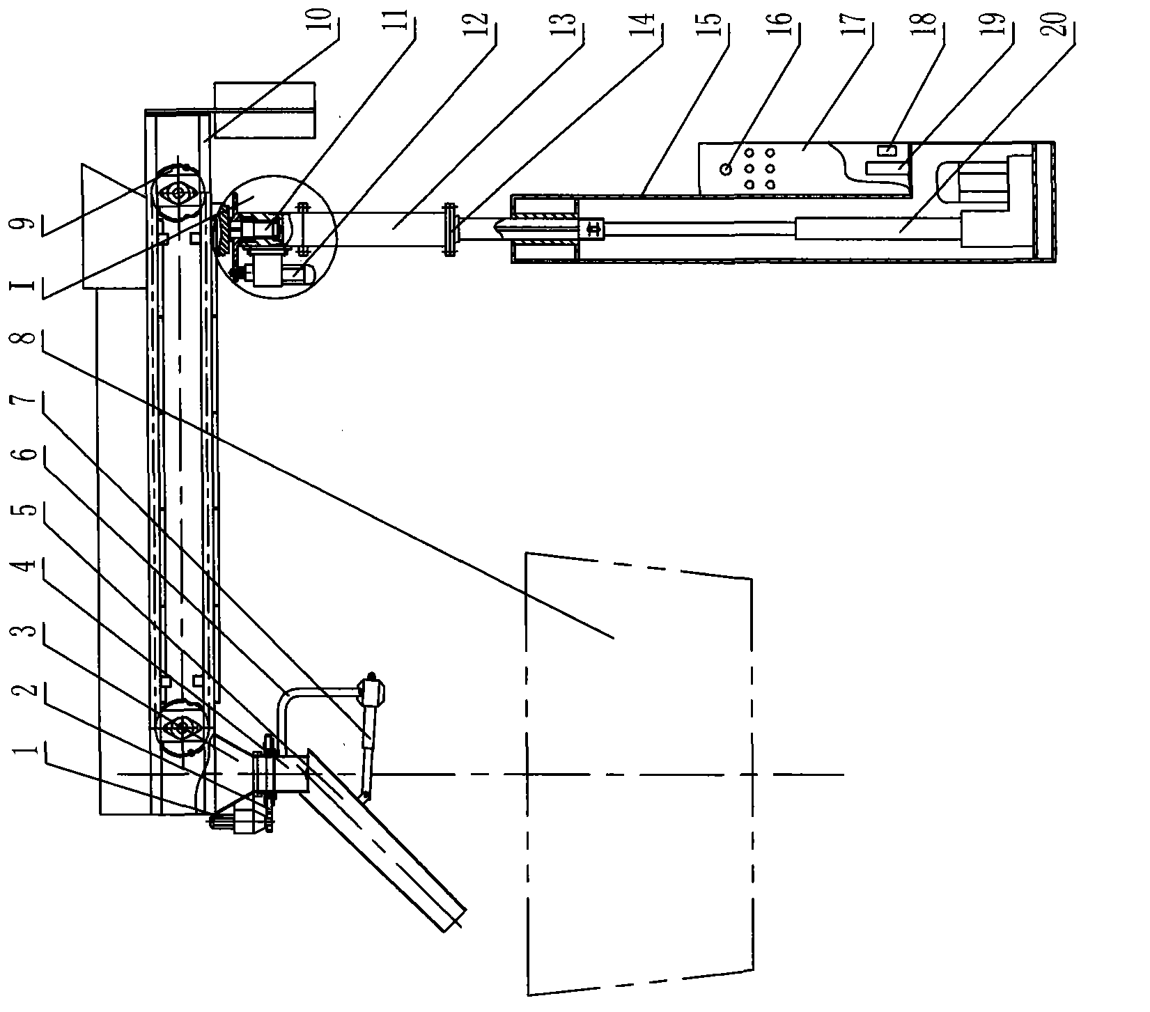
[0009] As shown in the figure, the present invention includes a lifting and turning device 14, a support 10, a conveyor 9 and a distribution device 6, the conveyor 9 is arranged on the support 10, and the distribution device 6 and the lifting and turning device 14 are respectively connected to the output end of the conveyor 9, The support 10 below the input end is connected, and the lifting and turning device 14 is also provided with PLC18 and frequency converter 19. The frame lifting and turning device 14, the conveyor 9, and the distributing device 6 are controlled.

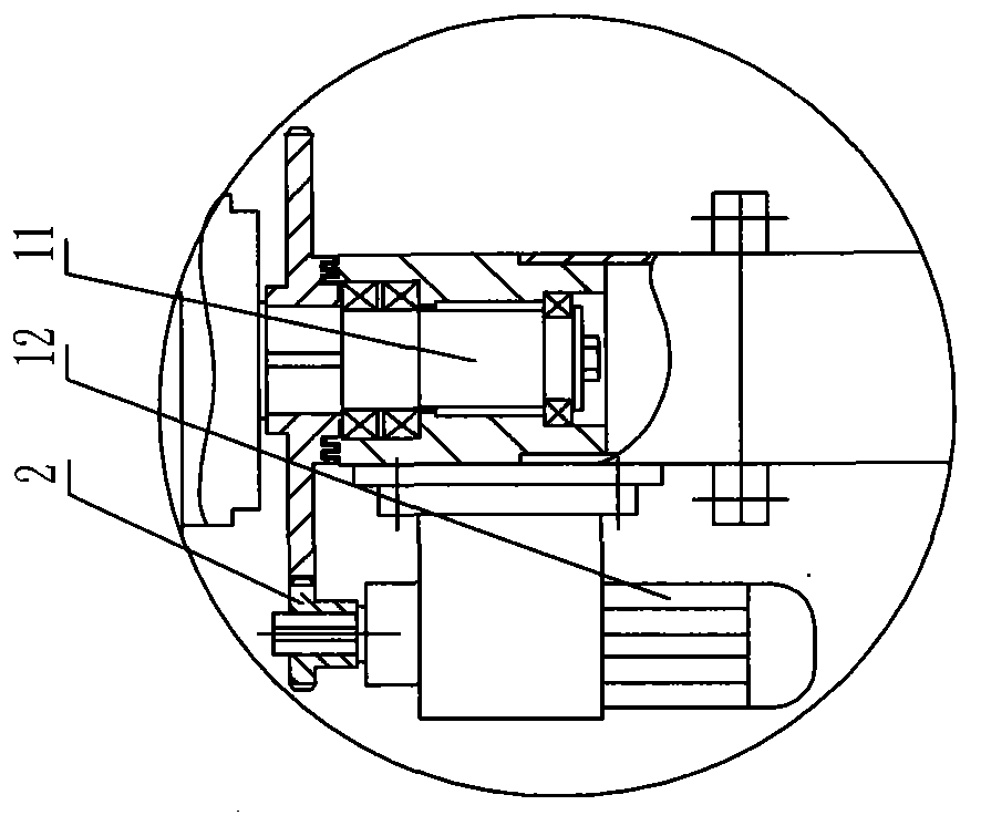
[0010] The lifting and turning device includes a support 15, a lifting electric push rod 20 arranged in the support 15, a slewing frame 13 connected to the upper end of the lifting electric push rod 20, a rotating shaft 11, and a rotating motor 12. The rotating shaft 11 and the rotating motor 12 pass through the gear 2 Connected, the lower end of the rotating shaft 11 is arranged in the slewing frame 13, and th...


PUM


Abstract

The invention relates to an automatic rice steamer filling machine with a rotatory center. The automatic rice steamer filling machine with the rotatory center is low in labor intensity, high in working efficiency and stable in rice steamer filling quality. The automatic rice steamer filling machine with the rotatory center comprises a lifting rotatory device, a support, a conveyor and a material distributing device. The conveyor is arranged on the support, and the material distributing device and the lifting rotatory device are respectively connected with the support which is arranged below an output end and an input end of the conveyor. The automatic rice steamer filling machine with the rotatory center is characterized in that a PLC and a frequency converter are further arranged on the lifting rotatory device, the PLC is connected with the lifting rotatory device, the conveyor and the material distributing device through the frequency converter, and the rack lifting rotatory device, the conveyor and the material distributing device are controlled through initialized programs of the PLC.

Description

technical field [0001] The invention relates to a retort loading machine for solid distiller's grains, in particular to a central rotary automatic retort loading machine. Background technique [0002] With the diversification of labor force employment, wineries of all sizes are facing the dilemma of being difficult to recruit roasting workers due to the high labor intensity. In the process of steaming wine and filling the retort, because it is required to sprinkle lightly and evenly, and put the retort on the air, manually shovel grain grains and sprinkle them on the place where the retort is filled with air, which is extremely labor-intensive and takes a long time. Through mechanization, reducing the amount of labor, reducing labor intensity, reducing dependence on the technical level of workers, shortening retort loading time, and improving production efficiency have become urgent problems for wine packaging factories. At present, some domestic manufacturers have develope...

Claims


Application Information

Patent Timeline
IPC IPC(8): B65G65/32B65G69/04
CPCY02P70/10
Inventor 黄先全王涛游玲
Owner 黄先全
Learn More