
Glove demolding counting machine and demolding counting method thereof

A counting machine and glove technology, applied in packaging automatic control, packaging, packaging protection, etc., can solve the problems of uneven arrangement of gloves, harsh production environment, and reduced production efficiency, so as to facilitate the arrangement of gloves, save height and space, and improve production efficiency effect

Active Publication Date: 2013-11-27
张家港宝翔机械有限公司
View PDF7 Cites 7 Cited by
  • Summary
  • Abstract
  • Description
  • Claims
  • Application Information

AI Technical Summary

Problems solved by technology

At present, the most primitive way of demoulding is to use manual demoulding, that is, to use manual pulling of gloves to separate gloves from the hand mold, and also rely on manual counting. This method consumes a lot of labor, but due to the harsh production environment, it seriously affects The physical health of workers and the counting accuracy of workers
In addition, there are also automatic demoulding equipment at present. This automatic demoulding equipment has the following problems: 1. The current automatic demoulding equipment generally has a counter. During the detection process, workers will remove unqualified gloves, so the corresponding hand mold There are no gloves on the top, and the current automatic mold release equipment will also count the empty hand molds, so that the count is not accurate, causing customer complaints
2. The current automatic demoulding equipment does not arrange the gloves neatly after demoulding, which affects subsequent packaging and reduces production efficiency

Method used


Image

  • Glove demolding counting machine and demolding counting method thereof
  • Glove demolding counting machine and demolding counting method thereof
  • Glove demolding counting machine and demolding counting method thereof

Examples


Embodiment Construction

[0034] The present invention will be described in further detail below through specific examples.

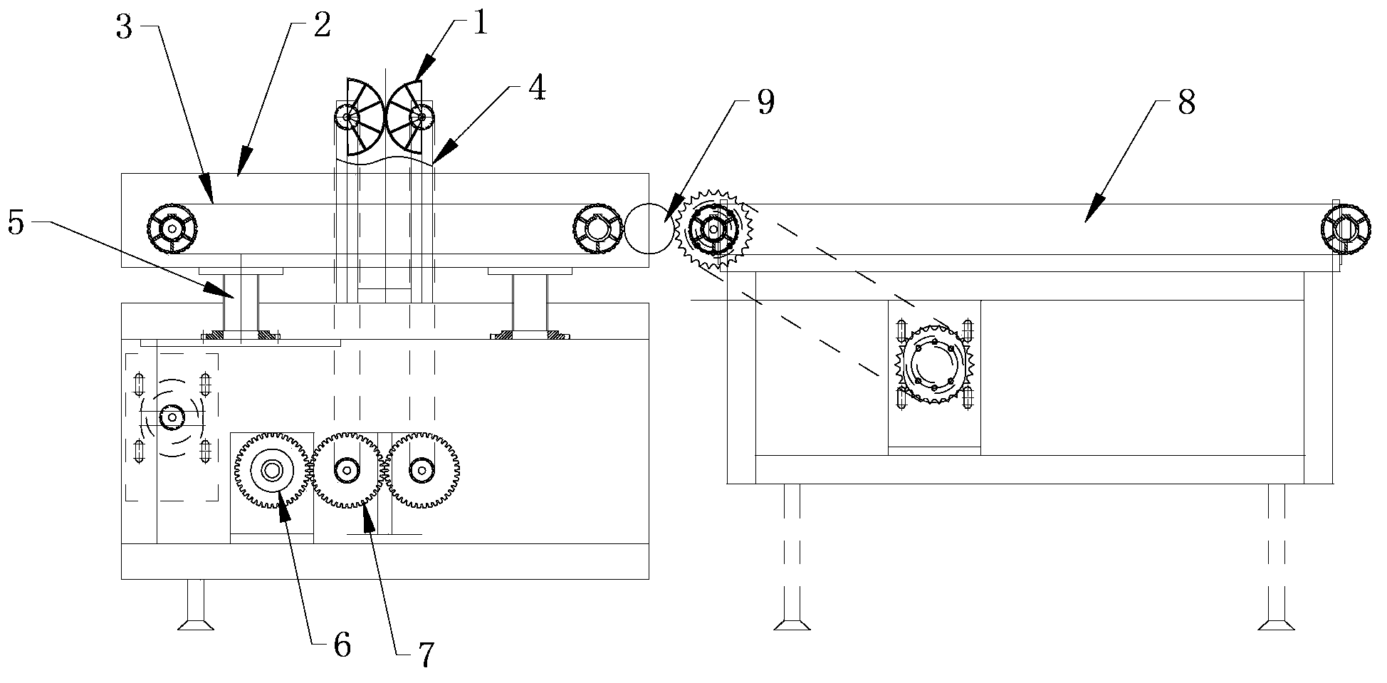
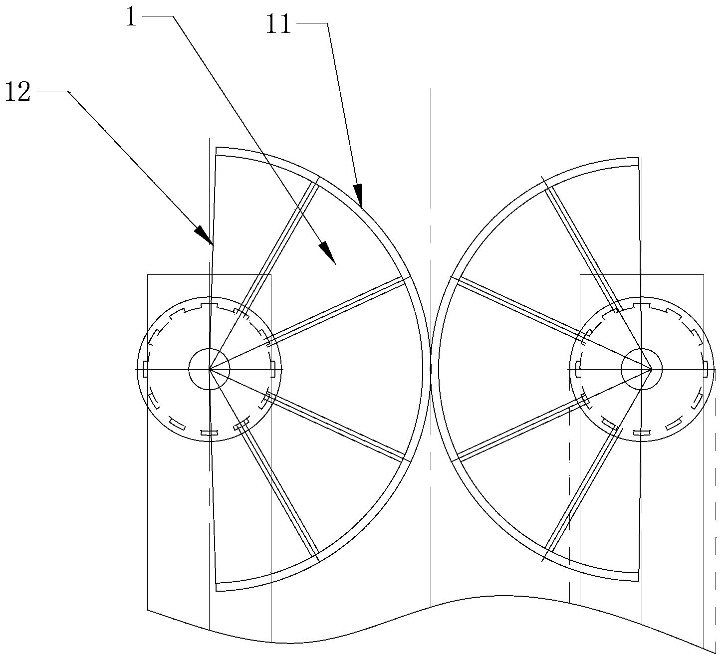
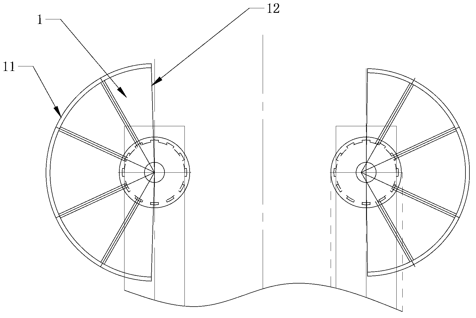
[0035] Such as figure 1 As shown, a glove demoulding counting machine includes a frame, a glove demoulding device and a belt conveyor 3, the glove demoulding device includes a support 4 and a pair of cooperating demoulding wheels 1, the support 4 is two poles, also can be a bearing, and each demoulding wheel 1 is rotatably installed on a bar, and this bearing 4 is fixed on the frame and is positioned at the side of frame. The gloves run successively from the sides of the rack along with the hand molds. The two stripping wheels 1 are driven to rotate synchronously by the stripping wheel driving device 6. The stripping wheel driving device 6 includes a driving motor, and a driving gear is installed on the output shaft of the motor, and the driving gear drives the stripping wheel through two synchronous gears 7. The mold wheel 1 rotates synchronously. Such as figure 2 , 3 As ...


PUM


Abstract

The invention discloses a glove demolding counting machine. The glove demolding counting machine comprises a machine frame and further comprises a glove demolding device and a belt conveying device. The glove demolding counting machine comprises a support and a pair of demolding wheels matched with each other, the support is fixed on the machine frame, the pair of demolding wheels is rotatably installed on the support, each demolding wheel comprises an arc-shaped force-applying wheel face and a conceding wheel face, the two demolding wheels are driven by a demolding wheel driving device to synchronously rotate, the force-applying wheel faces of the two demolding wheels are matched when opposite to each other so as to be contacted with gloves, and a conceding space is formed when the conceding wheel faces of the two demolding wheels are opposite to each other. The conceding space enables the gloves to enter an opposite range of the two demolding wheels conveniently, a counting sensor is installed on the support near the demolding wheels, and the belt conveying device is installed on the machine frame and the conveying downstream sides of the glove demolding device and used for arranging and intermittently conveying the demolded gloves. The glove demolding counting machine can be used for accurately and rapidly demolding and counting the gloves, production efficiency is improved, and labor cost is reduced.

Description

technical field [0001] The invention relates to a glove demoulding and counting machine, in particular to a glove production line for demoulding and counting equipment after pre-demolding. In addition, the invention also discloses a demoulding and counting method of the demoulding and counting machine. Background technique [0002] At present, in the glove production line, the hand molds are glued, dried, cooled, curled, pre-demoulded, demoulded, counted, and packaged. In the entire assembly line, demoulding and points are more important links. Demolding is to pull the pre-demolded gloves from the hand mold, and the points are to count the qualified gloves for shipment. At present, the most primitive way of demoulding is to use manual demoulding, that is, to use manual pulling of gloves to separate gloves from the hand mold, and also rely on manual counting. This method consumes a lot of labor, but due to the harsh production environment, it seriously affects The physical ...

Claims


Application Information

Patent Timeline
IPC IPC(8): B65B57/20
Inventor 肖品忠
Owner 张家港宝翔机械有限公司
Learn More